
by Shawn Burke, Ph.D.
OVERVIEW
Form drag – the non-friction, non-wave component of drag that arises due to the presence of a hull in flow – is defined and derived using momentum analysis. The so-called “drag equation” is developed using the magic of dimensional analysis. Form drag is shown to be one part of total hull drag, consistent with superposition and the drag equation’s quadratic form.
INTRODUCTION
Straighten your arm out in front of you, with your hand flat and parallel to the floor. Now briskly move your hand side-to-side, arm straight, and notice the sensations of air passing it.
Next, repeat this experiment with your hand still flat, but now held vertically (e.g., perpendicular to the floor), briskly moving your hand side-to-side, arm straight. Notice anything different? Do you feel more force distributed over your palm in this orientation than before?
This simple experiment is even more dramatic[1] if done by sticking your arm out the window of a moving car. With your hand horizontal the air rushes past it. With your hand held perpendicular to the airflow the amount of force on your hand can be quite large.
Why are the forces your experience in these two cases different? If you said “friction,” note that the friction drag force is proportional to the surface area of an object – here, your hand. The surface area of your hand doesn’t change whether you hold it vertical or horizontal. So while friction drag is present in both cases, there’s something else going on.
The simple answer is form drag.
Form drag arises from the mere presence of an object in a moving fluid. As we’ve noted before, if we adopt a hull-centric (or equivalently, a paddler-centric) reference frame a hull moving forward is hydrodynamically equivalent to a stationary hull with water moving past it. So when you’re in your canoe, kayak, dragon boat, or SUP you’ll notice a difference in drag force if you try to move the hull straight ahead versus trying to side-slip it. We all know that a streamlined hull moves fairly well straight ahead, akin to when your hand’s cross section is aligned with air flow past it in the example above. But when you draw a hull 90-degrees to the side it’s like trying to slide a barn door through the water. The difference between these two cases suggest that form drag depends on the shape of the hull, or rather the shape of the hull presented to the flow. So what is form drag, and where does it come from?
SAY HI TO MR. BERNOULLI
Since form drag is a different phenomenon than friction drag you might be tempted to analyze it using so-called inviscid (e.g., friction-free) fluid mechanics. Many of you will be familiar with Bernoulli’s equation, which describes inviscid flow in terms of fluid pressure and flow speed. A “Bernoulli analysis” would proceed as follows. Consider the plan view of a hull as shown in Fig 1.
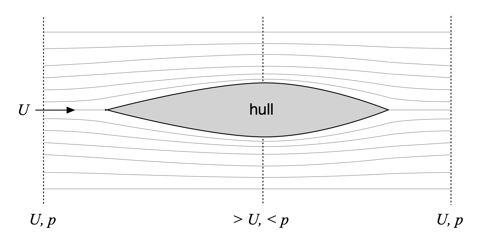
Figure 1: Plan view of inviscid flow around a hull.
A uniform flow moving left-to-right with speed U impinges on the hull. The hull’s keel is aligned with the flow direction. A series of streamlines are shown to flank the hull’s port (left) and starboard (right) sides. Streamlines are curves that are tangent at every point with the local flow direction. Far away from the hull the streamlines are parallel. But the streamlines are squeezed together more and more as the flow passes the widest point of the hull, then spread apart downstream. Since there can’t be any shear forces behind the stern – remember, this is a friction-free model – the water that split into two halves at the bow has to rejoin behind the boat, precisely. This means that the flow has to speed up at it approaches the widest point of the hull, then slow down thereafter until it once again equals the free stream flow speed U. Everything has to match up because no water is lost, a consequence of conservation of mass.
Bernoulli’s principle requires that energy in the flow be conserved. In this friction-free model there are two energy sources: kinetic energy due to the water’s motion, and potential energy in the form of pressure that can do work. As the figure suggests the uniform flow upstream and downstream of the hull both have the same flow speed U and pressure p. Since the flow speeds up midships the kinetic energy is greater there than at the bow. And because energy is conserved the potential energy must decrease by midships as well.
Most of us have an intuitive idea of what pressure is. But we often confuse force – which has a direction, and thus is a vector quantity – with pressure. Pressure is isotropic, which means it has no direction inside the fluid, just magnitude. If you have every inflated a tire or a basketball, you know that pressure pushes the walls of these flexible objects outwards. Once inflated neither tires nor basketballs fly away so there are no unbalanced forces. This means that the walls of the tire and basketball, subject to an internal pressure, achieve an equilibrium. The inflated tire or basketball are always exerting an inward-directed elastic force to maintain their shape. Newton’s Third Law requires that that all balanced forces have equal magnitude and opposite direction. This means that the air pressure inside is exerting an outward-directed force against the walls of these objects to balance the competing inward-directed elastic force. Pressure, then, acts like a distributed force on surfaces, directed perpendicular to the surface at every point over its entire extent.
For our hull this means that at the bow and stern, where the flow is nearly the free stream flow, there are equal pressures and thus equal forces which press against the hull. These are greater than the pressures that act amidships because of Bernoulli: where there is a faster flow speed there must be a reduced pressure. The pressure distribution can be summed over the area of the hull to determine the net force in the horizontal (x–y) directions since force is the product of pressure and area, directed perpendicular to the hull at every point. Any net force will be either a propulsive force, or a drag force.
Doing this calculation for our inviscid flow around the hulls leads to a net force of zero. Try it for yourself and see – you’ll find that the rearward-directed force components in the front half of the hull are canceled by the forward-directed force components in the back half, just as the keel line-directed force components on the port and starboard sides of the hull cancel each other. This means that a simple Bernoulli analysis will not tell us anything about the drag force since it implies – within the assumptions of the model – that there is no net force on the hull that would cause it to accelerate or decelerate. Time to move to a model that incorporates real-world phenomena. Like a wake, which is conspicuously missing from Fig. 1.
OF WAKES AND VELOCITY DEFICITS
Those of you who have ridden the stern of another paddled hull know that the flow behind the lead boat isn’t smooth and uniform; it’s nothing like the flow depicted in Fig. 1. There are whorls and eddies, and some inflow directed toward the lead boat’s stern – this inflow is in part what you’re riding when on the stern. Most of us would recognize that there is a wake behind the lead boat, and this wake gets wider the further back you are from their stern.
The stern wake behind a hull is shown conceptually in Fig. 2’s plan view. As in our Bernoulli analysis we adopt a hull-centric frame of reference, which transforms hull speed U into a uniform fluid inflow of the same speed having parallel streamlines. The wake has a fan shape astern of the hull. Across the width and height of the wake the velocity decreases compared to the free stream speed U; it also varies with distance from the stern so the velocity profile shown in the figure is at a fixed distance astern. The particulars of the fluid velocity distribution there aren’t as important as noting that, on average as you move across the wake, it is less than the free stream speed U. This is what appears to pull you in to the lead boat’s stern since the trailing hull is experiencing “slower” water. Further, outside the wake the flow is assumed to once again have the uniform free stream flow speed U.
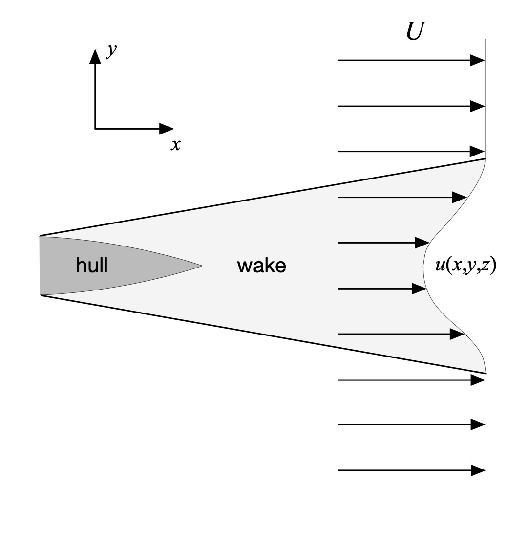
Figure 2: Plan view of the wake behind a hull.
Having established the particulars we can determine what role the wake plays in drag. We’ll do this using the principle of mass conservation, and Newton’s Second Law.
Consider the hull and water system depicted in Fig. 3. A box-shaped slug of water surrounding the submerged portion of hull is shown, along with various marked areas along the box’s surfaces. The particular shape of this water volume isn’t important; a rectangular shape was chosen merely for convenience.
Downstream of the hull a fan-shaped wake subtends an area denoted as Ad2; the ‘d’ indicates this surface is downstream. This area is located far enough downstream of the hull such that the flow velocity outside of it is equal to the inflow flow velocity U. There is also a U-shaped area Ad1 coplanar with but not overlapping Ad2. Upstream of the hull there is an area Au2 that is a colinear projection of the downstream area Ad2; the ‘u’ indicates this surface is upstream. There is a U-shaped area Au1 coplanar with but not overlapping Au2. And finally, the other sides of the box have an area As. In total these surfaces define the outside of a so-called control volume.
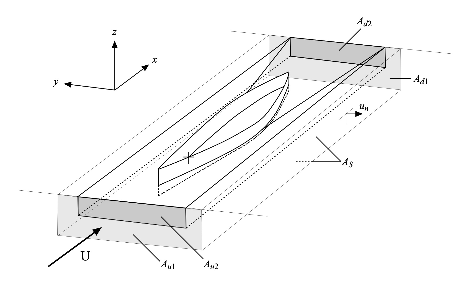
Figure 3: Hull perspective view with control volumes.
While water may enter and exit the control volume, it is neither created inside this space nor does it somehow disappear there, either – no sources or sinks. Consequently, any mass flow of water into the control volume must be balanced by an equal amount of mass flow out of it. This is the fluid mechanical principle of continuity – what comes in must come out, somewhere. Fluid mass flow is defined as the product of the water’s density r and its fluid velocity summed over the area through which it passes, with units of mass divided by time. Fig. 3 shows that water can flow through the upstream areas Au1 and Au2 with inflow velocity U, and consistent with our assumption of flow uniformity it flows out of the area Ad1 with velocity U as well. Water flows out of the wake’s cross-sectional area Ad2 at velocity u, as suggested in Fig. 2. And finally, any fluid that leaks out of the sides of the control volume does so with flow velocity un, directed perpendicular to any of the top, bottom, and side surfaces of the control volume.
This summing over an area is another way of saying “integration.” As a result, since the two inflow terms (the positive ones) and three outflow terms (the negative ones) must balance,

The lower limits of these integrals just a shorthand for the area over which the mass flow is summed, with dA denoting the area differentials over which the sum is performed. This saves us using surface integral notation. Since Au1 and Ad1 are equal the first and third terms cancel, leading to an expression for conservation of mass flow for our system as

Newton’s Third Law requires that any net force on the hull – here, the drag force – must be equal to the fluid mechanical forces acting on it. These exogenous forces arise from Newton’s Second Law, which states
The Rate of change of momentum of a body is equal to the resultant force acting on the body, and takes place in the direction of the force.
Here, the “body” is the mass of fluid that passes through one of the surfaces defined above. Its momentum P over a differential area dA is the product of its mass and velocity

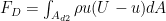
The rate at which momentum enters or leaves one of the surfaces is the product of momentum times velocity, which over a differential area dA equals

Summing the components of the rates of momentum change over their respective areas gives us an expression for the drag force in terms of the forces over each of the control volume’s five areas,

The free stream velocity U is constant over the y-z plane outside of the wake. This allows U to be moved outside of the integrals, whereupon we can cancel certain terms to provide the intermediate result

Substituting the expression we derived above for fluid mass continuity yields a simplified expression for the drag force:
If the wake velocity u is everywhere equal to the free stream fluid velocity U then U – u equals zero, and the integral goes to zero as well. This limiting case is our wake-free Bernoulli model, which had not form drag. Check! Since the wake fans out from the stern we know from continuity that the wake velocity u summed over the area subtended by the wake must always be less than the free stream velocity U. As a result, the drag force is always greater than zero, even in the absence of friction. The drag force derived above is called the form drag; the term U – u is called the wake deficit or the velocity deficit of the wake. Form drag arises because objects in flow generate a wake, causing the flow’s momentum to change. And changes in momentum give rise to force. The form drag’s particulars depend on the hull design, and are specific to each and every different hull, just like the form drag of your hand changed depending on its shape (e.g., orientation) as you moved it through the air.
THE DRAG EQUATION
In Part 3: The Rough Stuff we considered the sources of friction drag. Any drag force acts in opposition to the direction of motion. And since forces sum – a concept called superposition – each component of drag can be added to determine the total drag acting on the hull. The sum of friction drag and form drag is called the parasitic drag. There is a third element of drag that is highly relevant for displacement hulls like canoes, kayaks, SUPS and the like, and that’s wave drag, which we looked at in Part 4: Shallow Water.
In various installments of The Science of paddling we’ve assumed that drag varies as the square of the hull’s velocity. Certainly, the form drag expression depends on products of velocities, so it has a velocity squared dependence. But where does the fundamental assumption of this squared dependence some from?
We can answer this question using dimensional analysis. When I first learned about dimensional analysis as an undergraduate I thought it was magic. In essence you list all of a problem’s relevant parameters, toss ‘em in a bag, shake, and an equation pops out describing what you are interested in. While this is a gross oversimplification, and I now understand the fairly sophistical mathematical foundation underlying dimensional analysis and see why it works, it is still magical.
For drag acting on a body in flow we’ll assume that these are all of the relevant parameters:
- The speed u
- The fluid’s kinematic viscosity
- The fluid’s density
- Some characteristic area of the body A, like its cross section
- The drag force FD.


Dimensional analysis proceeds by positing an equation expressed in terms of a function f of all these parameters:

This may seem pretty abstract; don’t worry, it is. The key takeaway is to recognize that the right-hand side of this equation, the number zero, is dimensionless. All of the parameters we listed above have dimensional units, like meters per second or kilograms per cubic meter. Zero has no units; it is nondimensional. This means that the function f must also be dimensionless (or if you prefer, free of dimensional units), and thus can be expressed in terms of a few nondimensional quantities.
Recall that we defined the transition of a boundary layer in Part 3: The Rough Stuff in terms of a Reynolds Number Re, defined in terms of a characteristic length L as
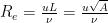
The Reynolds number is a dimensionless quantity constructed from our list of five relevant parameters. For convenience we’ve assumed that the characteristic length L can be expressed in terms of the square root of the characteristic area A. Don’t worry about the specifics of what A or L are right now; it all works out to within a multiplicative constant at the end[2].
The other nondimensional quantity that pops out from our list of relevant parameters is the ratio of the drag force to the product of the flow’s dynamic pressure times the characteristic area; this product has the dimensions (units) of force. This means our abstract function f becomes a bit less abstract,
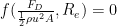
Because the only unknown in this equation is the drag force, we can rewrite this as

or

where we have defined CD as the drag coefficient, expressed in terms of a new function r of the Reynolds Number Re. This is the so-called Drag Equation.
What exactly is the function r? At the risk of seeming flip, it’s not that important unless you want precise answers for some particular case. Yeah; fluid mechanics is like that. And that’s OK. Note that over the range of speeds we cruise the Reynolds number only changes so much, so since r is a function of the Reynolds number it too may only change so much. On the face of it this appears to be a weak argument but let’s see where it leads us.
Note how dimensional analysis shows that the drag force varies as the square of the flow speed u. We’ve used this quadratic form for drag in a variety of Science of Paddling articles. And as we saw in Part 14: Kind of a Drag a paddled hull really does exhibit this type of behavior when using an exact solution to an unforced governing equation modeling hull motion that incorporates quadratic drag. And this governing equation used a constant drag coefficient CD. As a result, empirical evidence indicates that the function r depends weakly on Reynolds number, or its speed component u. This means that it is reasonable to assume the drag coefficient is a constant for a given hull; it’s a very good approximation
And what of the function r’s dependence on the square root of the characteristic area A? This merely reflects how the drag coefficient is specific to the object experiencing drag. The area A lumps together a number of geometric effects into one parameter, so if you change the hull design you change the drag coefficient.
Similarly, the drag coefficient of a paddle, which we employed in Part 11: About the Bend, is also assumed to be constant. But what if you only partially submerge the blade? In that case you haven’t changed the blade design – it’s the same paddle – but you’re presenting an object to the flow that is different than the entirety of the blade. What is in the water, which is the part that counts, is different. This means it’s a tenuous assumption at best to use the same drag coefficient to model a partially submerged paddle blade as for a fully submerged blade.
SUMMARY
In this installment of the Science of Paddling series we considered form drag – the non-friction drag that arises due to the presence of a hull in flow. We showed that a simple inviscid (friction-free) analysis based on Bernoulli’s Principle failed to account for the loss of momentum created by a wake. A more representative analysis using Newton’s Second Law let us derive the form drag force in terms of a wake deficit, the difference between the hull speed and the entrained flow speed within the wake.
We also developed the so-called “drag equation” using the magic of dimensional analysis. Form drag is one part of total hull drag, consistent with superposition and the drag equation’s quadratic form. In light of experiment, it is reasonable to use the drag equation to model the drag force as depending on the square of hull speed. Since it depends on hull (or paddle) geometry the form drag coefficient is hull (or paddle) specific.
v. 1.0
(c) copyright 2020 by Shawn Burke, all rights reserved. See Terms of Use for more information.
REFERENCE
Wen-Hsiung Li and Sau-Hai Lam, Principles of Fluid Mechanics, Addison-Wesley (1964).
© 2020, Shawn Burke, all rights reserved. For more information see Terms of Use.