by Shawn Burke, Ph.D.
SUMMARY
Hull speed is characterized via momentum and changes in momentum. Increases in speed / momentum, are expressed in terms of the product of three parameters: paddle force impulse, stroke duty factor, and stroke cadence.
INTRODUCTION
I have periodically had discussions – well, maybe arguments – with paddlers and runners about ways to parameterize the competitive side of our sports. Aside from finishing time or speed what are the “best” things to measure so as to understand whether a particular element of paddling or running form makes us faster. Or slower.
Running is my favorite case in point. Intuitively, we might think that if each stride is longer, and the number of strides per minute (aka, cadence) is higher, then we run faster. Which is of course true. Plus, stride length and cadence are easy to wrap your head around. But I contend that a faster cadence and longer stride are the result of better underlying running dynamics, not the cause. Cadence and stride length are a step removed[1] from the underlying cause(s).
Consider the following figure from U.S. Patent Number 6,018,705 awarded to Gaudet et al on January 5th 2000. This figure is a plot of pace vs. foot contact time – the time your foot is on the ground – for running and walking. The plot comprises two lines, with an abrupt transition connecting the two. The left line and its slope relates foot contact time with running pace, while the right line and its slope relates foot contact time with walking pace. The abrupt transition reflects changing biomechanics as we move from walking (where at least one foot is on the ground at all times) to running (where there are times where both feet are off the ground). What I find most significant about this plot, which is derived from experimental data and is remarkably repeatable, is that neither stride length nor cadence are shown to play a role in pace, which is the reciprocal of speed. A shorter foot contact time corresponds to a faster pace, period. So if you want to identify a trainable parameter to increase running speed, choose foot contact time.
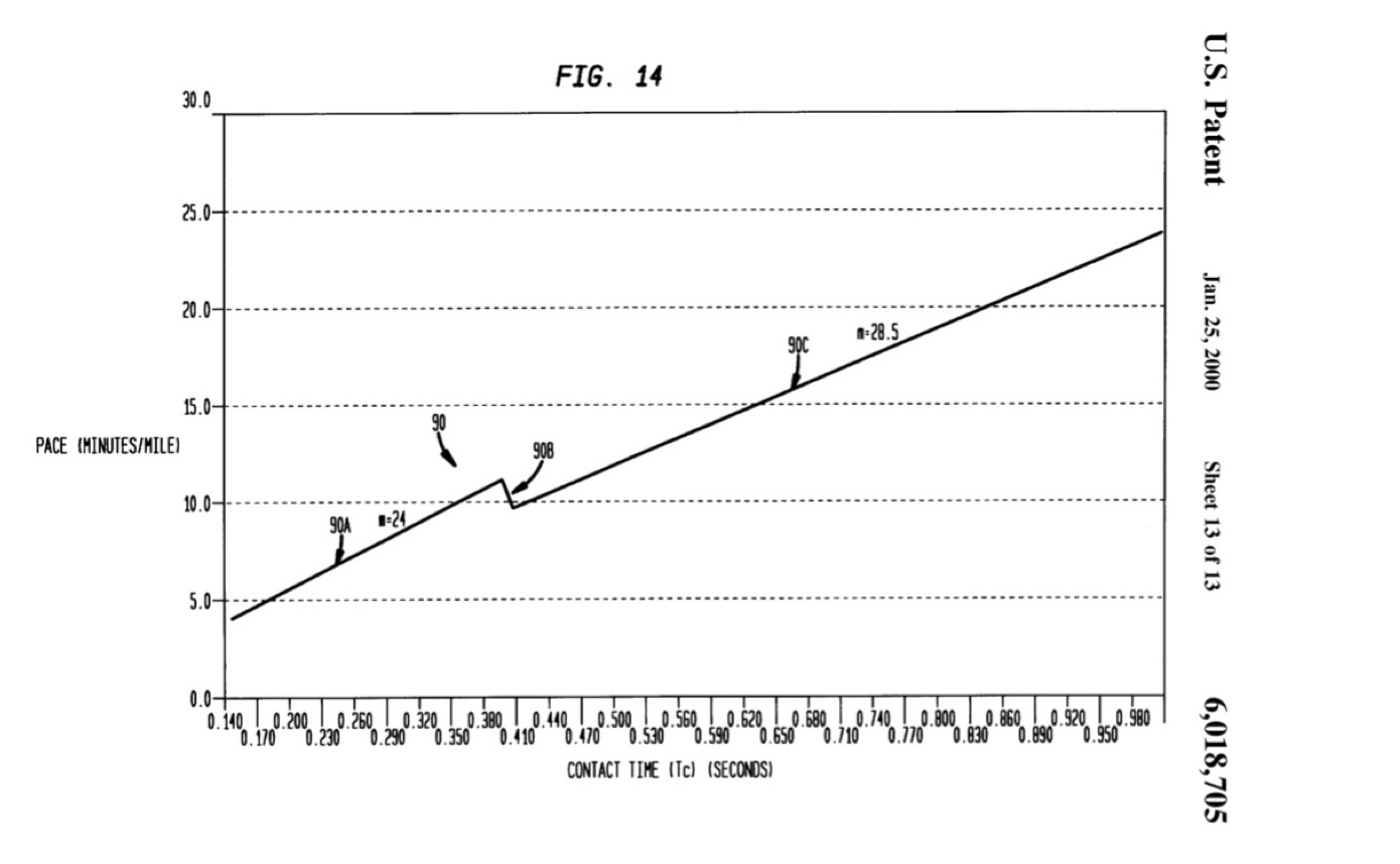
Figure 1: Pace vs. foot contact time for runners and walkers (from U.S. Patent No. 6,018,705).
What gives rise to shorter foot contact times? Further analysis of runners shows that speed is related to the ability to exert large forces, quickly. As Clark and Weyland[2] noted,
“Contrary to intuition, fast and slow runners take essentially the same amount of time to reposition their limbs when sprinting at their different respective top speeds. Hence, the time taken to reposition the limbs in the air is not a differentiating factor for human speed. Rather, the predominant mechanism by which faster runners attain swifter speeds is by applying greater forces in relation to body mass during shorter periods of foot-ground force application.” [emphasis mine]
So there goes stride length and cadence as causative factors.
I read Clark and Weyland’s paper and immediately thought of the physics principle relating impulse and momentum. When you hit a baseball with a bat you are changing the ball’s momentum by applying a force over a finite period of time. Ditto for driving a golf ball off a tee using a club. This force-time input that changes the struck object’s momentum is called impulse.
In a way each paddle stroke is like hitting a golf ball; at least as far as physics is concerned. You exert a paddle force over a period of time, and thus change the hull’s momentum. Cool. But what about exerting large paddle forces… quickly? Or is this stretching the running analogy too far?
In what follows we’ll explore impulse and momentum in order to describe how a hull moves in response to paddle strokes. Then we’ll look at what I call the “paddle cycle,” along with cadence, to see if something akin to running’s concept of large contact forces exerted over short times can be used to parameterize every aspect of paddling speed. And I do mean every. Along the way we’ll identify actionable training focuses for various elements of the paddling stroke.
MOMENTUM AND IMPULSE
As you’ll recall from Part 5: What Moves You, the motion of a paddlecraft can be described in terms of its momentum p. Momentum is the product of the craft’s mass, plus the mass of its occupants and gear, times its velocity,

In general momentum is a vector (e.g., directional) quantity because velocity is a vector. For this article we’ll only look at the magnitude of velocity in the direction of motion, which is commonly referred to as the hull’s speed. So hereinafter ‘v’ refers to speed in the direction of motion; it is a scalar quantity.
Since the mass of the hull and its contents m is fixed, a change in momentum ∆p then corresponds to a change in its speed ∆v,

This change in speed is illustrated in Fig. 2. With each stroke, in the reference frame of the water[3], the hull speeds up during a stroke’s power phase, then slows down because of drag forces until the next stroke. This cycle repeats itself stroke after stroke.
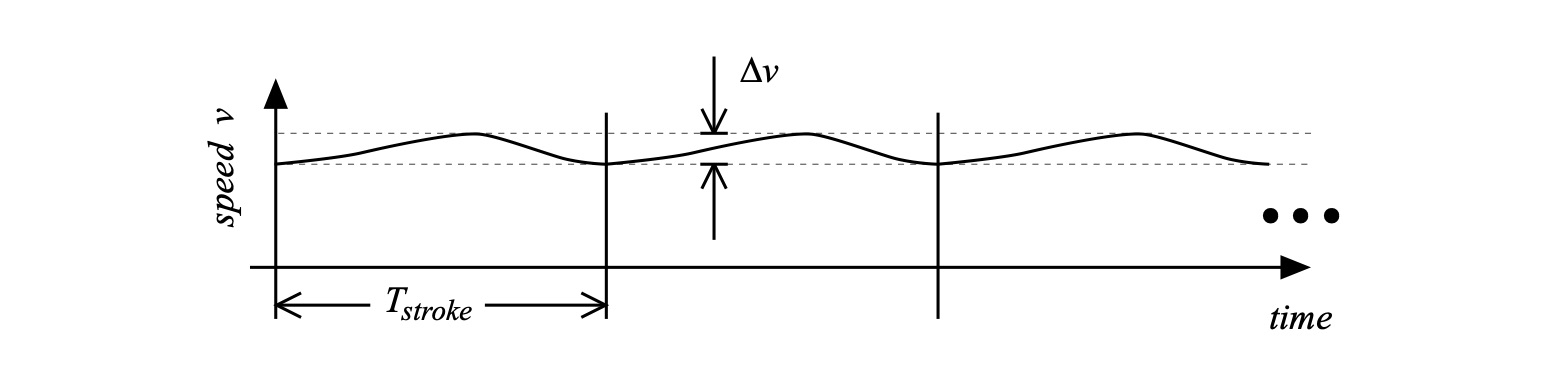
Figure 2: Hull speed variations over time (not to scale).
This change in speed can be cast in terms of conservation of momentum vis a vis the momentum imparted by a paddle moving water opposite to the direction of motion (see Part 5: What Moves You) as well as in terms of the force exerted by the paddler (see Part 11: About the Bend). We’ll draw from both of these in the ensuing analysis.
First, recall that the hull’s acceleration a can be expressed in terms of the time rate of change of its speed. Rather than writing this using a derivative we’ll express the time rate of change in terms of the change in velocity ∆v over a corresponding interval of time ∆t,
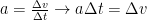
Using our expression for the change in momentum ∆p and substituting,

where we have used a form of Newton’s Second Law to equate propulsive force F with the product of the total mass m and acceleration a. This equation shows the relation between a change in momentum p, the propulsive force F, and time t. In physics this product of force F over the time interval ∆t is called impulse, and is typically represented by the letter J,

Think of impulse as the input that leads in a change of momentum. By exerting a paddle force over a stroke’s power phase we change the hull’s momentum, which means we change its speed[4]. This is evident to anyone that has paddled a canoe, kayak, surfski, dragon boat, outrigger, SUP, or anything else. And the expression above for impulse will give us insight into what makes a hull go fast. Or slow.
First, let’s understand what we mean by this time interval ∆t. Much like walking or running has a gait cycle that corresponds to the various elements of leg movement during human locomotion (lift-swing-step-stance) the paddle cycle can be broken down into a sequence of events with corresponding durations as shown in Fig. 3.
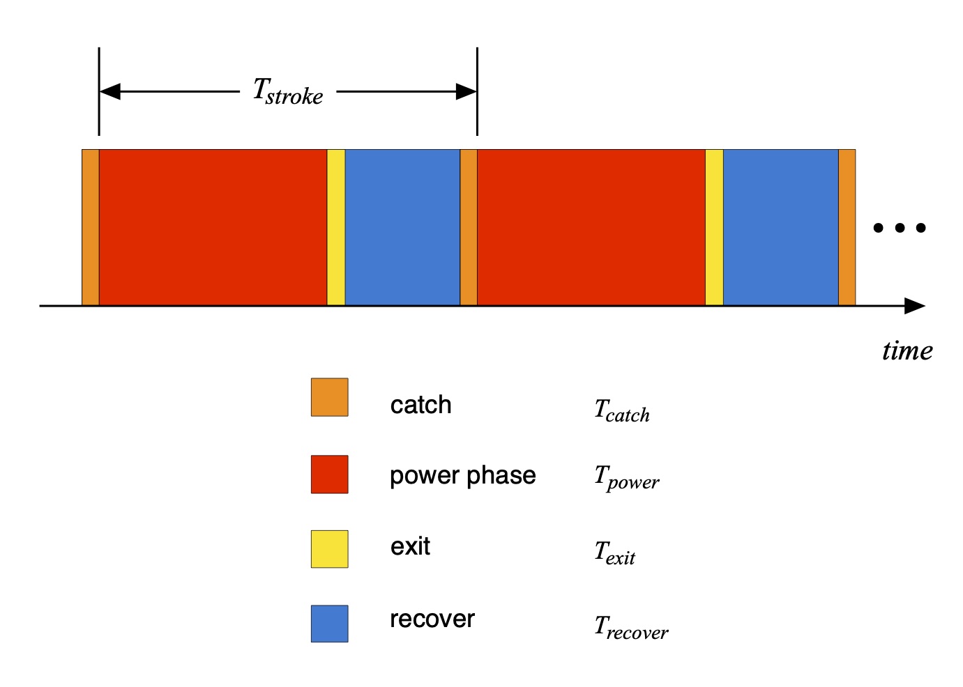
Figure 3: The “paddle cycle” elements and corresponding times.
In order to be precise in our use of terms we’ll define here the power phase as the event and corresponding time over which a paddle force is exerted opposite to the direction of travel; the exit as the event and corresponding time over which the blade is being drawn out of the water; the recovery as the event and corresponding time over which the blade is out of the water and moving forward; and the catch as the event and corresponding time during which the blade is being inserted into the water, and where no force opposite to the direction of travel is being exerted. This all may seem like a mouthful, even overkill, and there are other ways of defining these terms. But we’ll need this level of precision in the ensuing discussion. Using these, the time duration of a stroke is then the sum of the time duration of each element,

Since ∆t must correspond to the time over which the force is exerted, ∆t is the duration of the power phase Tpower.
What we mean by ‘force’ in the expression for impulse J can be a bit confusing; physics can be sneaky that way sometimes. However, since our analysis is based on incremental changes of momentum, velocity, and time, we should understand the force F in the expression above for the impulse J is the average propulsive force over the power phase.
Since we’ve all paddled we know the actual paddle force varies over time, as idealized in Fig. 4. The average paddle force is also shown as the dotted horizontal line.
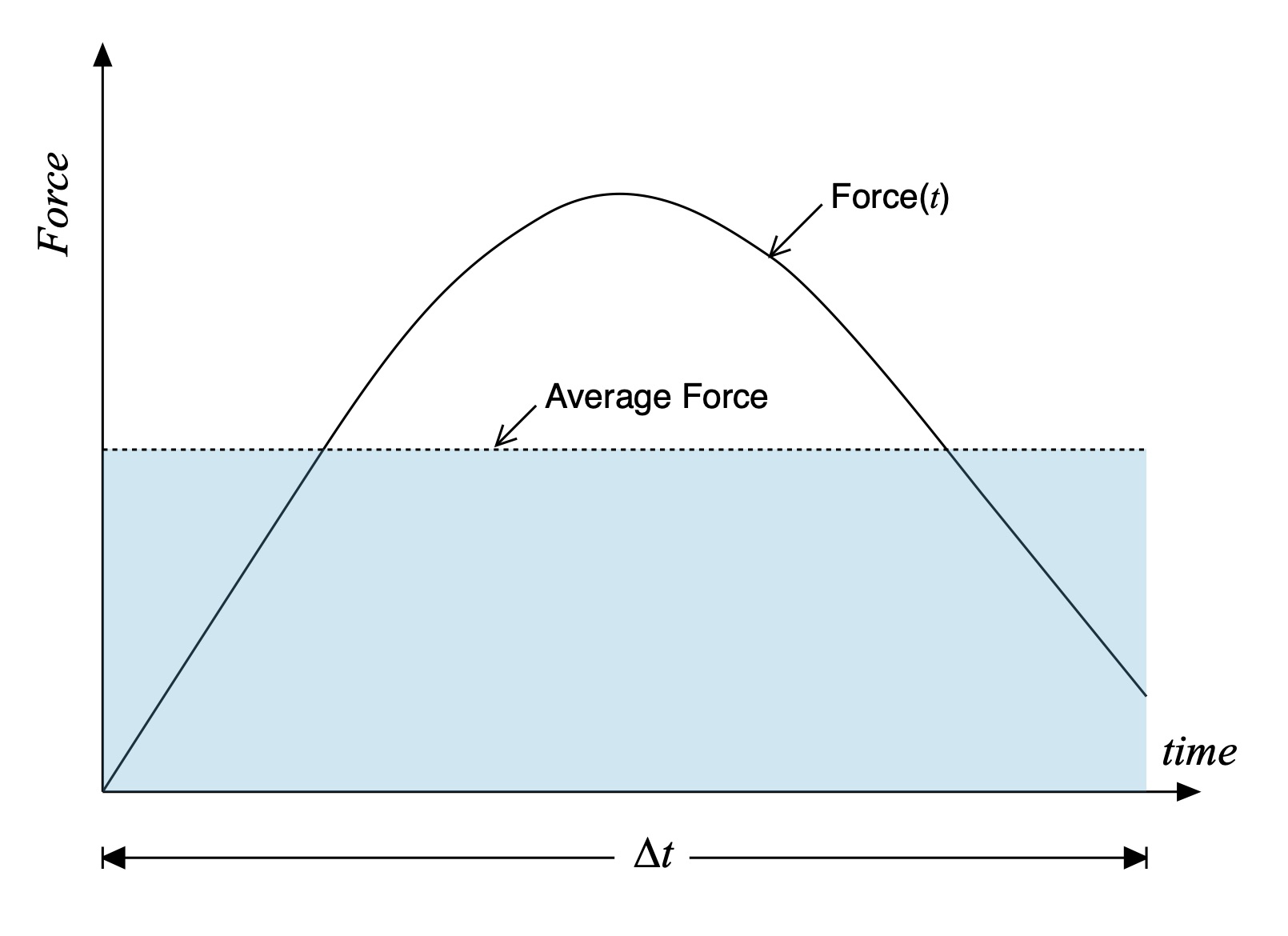
Figure 4: Paddle force vs. time along with its average.
Over the power phase the average propulsive force is constant – that’s what makes it an average! And the time length of the power phase is known, or at least measurable. Consequently, the area of the pale blue rectangle shown in Fig. 4 equals the impulse since it corresponds to the average propulsive force multiplied by the duration of the power phase ∆t. That’s how you compute the area of a rectangle.
Those of you who are familiar with calculus will recognize that this averaging and area computation corresponds to integration, an operation that is often explained in introductory calculus courses as “the area under a curve.” This means the impulse J can be expressed in terms of the actual time-varying force F(t) via the integral
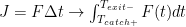
The limits of integration are written in a precise but peculiar way. Since the force average is only computed over the power phase – when force is actually being exerted – the lower limit is the moment in time at the end of the catch, hence the ‘+’, and the upper limit is the moment in time at the initiation of the exit, hence the ‘-‘.
DUTY CALLS
So now we understand how momentum is imparted to a hull plus paddler(s) via impulse for a single stroke. As we know, a paddler may exert a great deal of propulsive force during the power phase, but the balance of their stroke cycle might include a long recovery. Further, a paddler may be able to put a lot of oomph into the water for a single stroke, then stop paddling; this is the “infinite recovery time” limit, and not particularly interesting. In other words, just focusing on the computation of a single stroke’s impulse isn’t sufficient for characterizing how a sequence of strokes moves a hull over time. We’ll quantify this using the concept of Duty Cycle.
For a cyclic system the Duty Cycle is the fraction of a period over which the system is active; you’ll see this term used to describe systems that employ pulse width modulation (PWM) such as stepper motor controllers and certain RF and wired communications protocols. We’ll parameterize the duty cycle for paddling via a Duty Factor ‘D’, which is the fraction of time over an entire stroke where there is a non-zero paddling force, as indicated in Fig. 5. The paddling “system” is ‘on’ when the paddler is exerting a force during the power phase, and it is ‘off’ the rest of the time.
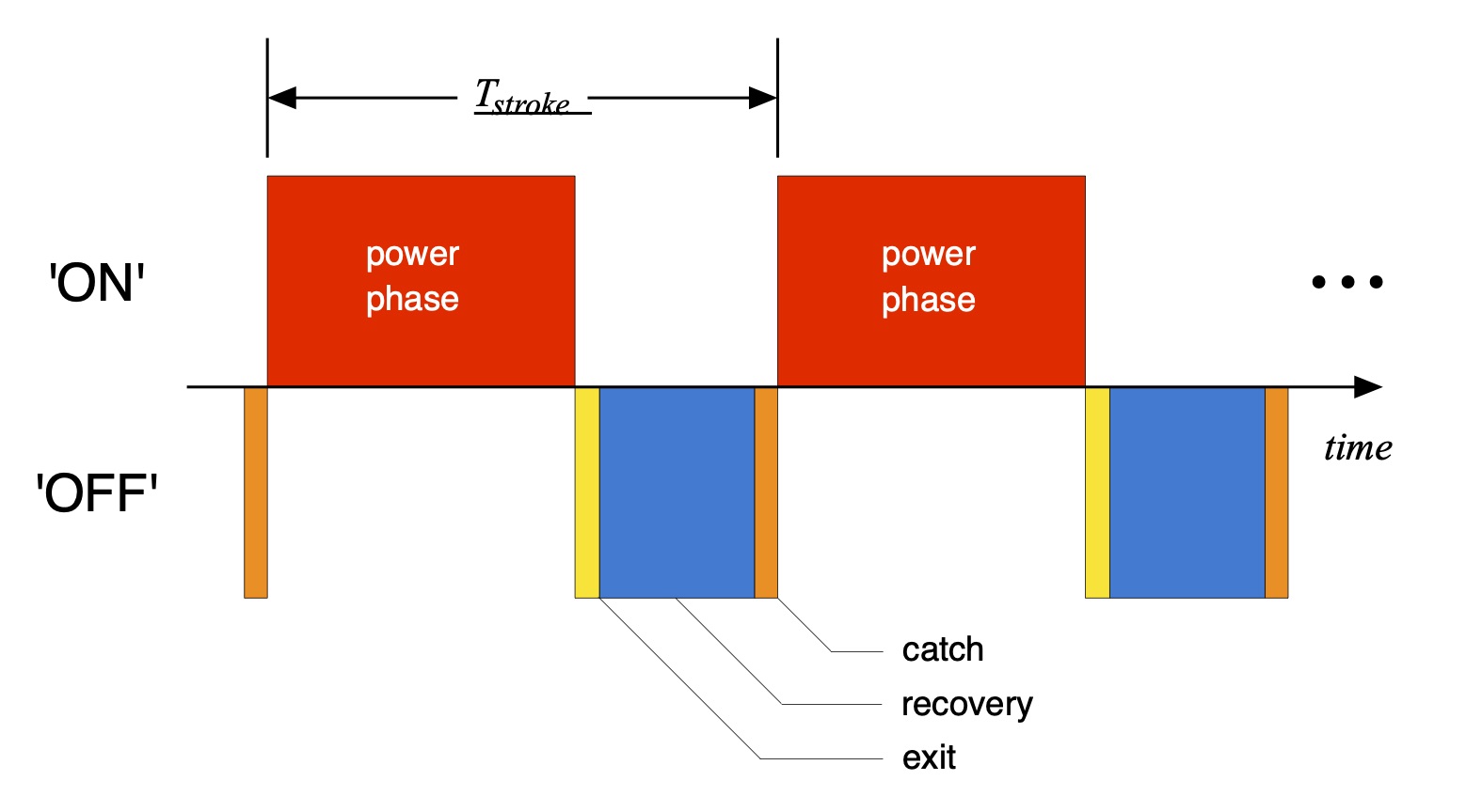
Figure 5: ‘On’ and ‘Off” portions of the paddling cycle.
The duty factor will range between 0 (e.g., no paddle force and thence no impulse at all) and 1 (e.g., zero exit + recovery + catch time). Since no paddling stroke in the real world is done with zero recovery time we note that D may get close(r) to 1 (or if you prefer, 100%) but never equal it.
Now for a particular stroke, which we’ll designate as stroke number ‘i’, the corresponding impulse weighted over the stroke can be represented by Jstroke[5] as

where Ji is the impulse over the power phase and Di is the duty factor corresponding to this i-th stroke. The product of impulse J and duty factor D represents an averaging of the impulse over the entire stroke. It addresses the case where a paddler exerts a large force (and therefore a large impulse) over the power phase, but has a slow exit, recovery, and catch. In that case Jstroke will be lower than for a paddler with the same impulse over the power phase but a faster exit + recovery + catch time. Its weighting by the duty factor provides a way to compare paddlers apples-to-apples for a given (total) stroke.
So now how do we compare paddlers who have different cadences, either within or across disciplines? The above parameterization lets us compare paddlers stroke-to-stroke who have the same total stroke time Tstroke. But the comparison is nebulous if they have different cadences, which is proportional to the inverse of stroke time. One paddler may have a slightly higher single-stroke weighted impulse but a longer stroke time (and a lower cadence), meaning they change the hull’s momentum fewer times over a longer time frame such as a minute, or even a race. The paddler with a faster cadence but lower weighted impulse may actually move the hull faster. And vice versa; we’ve all seen examples of both types of paddlers.
In order to characterize momentum change over a time period longer than a single stroke we’ll compute the total impulse over a number of consecutive strokes. Over N strokes the average weighted impulse is the sum of the individual weighted stroke impulses divided by the number of strokes,

One can idealize the average weighted impulse over those N strokes as if a paddler were executing N perfectly uniform and consistent paddle force curves, each having the same duration and duty factor.
To characterize and compare paddlers one then multiplies the average weighted impulse by the number of strokes performed over a particular unit of time, such as a minute. Interestingly enough, the number of strokes performed per minute is the paddling cadence C. Consequently, on a per-minute basis the total hull momentum change – e.g., what moves a hull faster or slower – is expressed rather simply as

(A quick aside: We know that paddlers come in all sizes and shapes. It can be instructive to normalize Jpaddle by a paddlers’ weight in order to calculate a non-dimensional metric, often referred to as specific impulse. This accounts for differences in paddler size which often correlate with differences in height and muscle mass.)
OK, SO WHAT DO I DO NOW?
The lure of the above expression for paddling impulse per minute is its simplicity, which may be summarily expressed in a “sliding average” over N strokes as

Breaking it out this way lets us investigate how we might optimize the total change in hull momentum.
First, you can increase stroke cadence to increase Jpaddle. However, cadence by itself is not sufficient to infer increases in hull speed. Cadence is a factor but not the sole metric defining speed.
Next, you can increase the stroke duty factor, e.g. the percentage of time you’re actually exerting a paddling force to move the hull forward. This is the same as making your total recovery time shorter with respect to the stroke time. So tell me something I don’t already know!
But referring back to Fig. 5 note that the total recovery time as defined here is the sum of the exit, recovery, and catch times; none of these contribute to force creation except to set up the paddler for the next stroke. Which gets to the question of whether a particular style of exit, recovery, or paddle blade entry makes you go faster: yes, but only if it minimizes your time not exerting a paddling force. Beyond that physics doesn’t care how you take the blade out, move it forward to recover, or enter the water.
The moral of this story is to always have a quick, deep catch so that you can start pulling and contribute to the area under the force curve. Whatever technique accomplishes this is best – you pick – and physics doesn’t discriminate. Then exit when there isn’t a lot of felt pressure on the blade since you’re neither contributing to the area under the force curve nor decreasing the exit and recovery time compared to the stroke time.
And finally, you can increase the impulse, which is the product of the average force over a stroke times the power phase duration. From Part 11: About the Bend we learned that one way to represent this time-varying force is by the equation

where 


We saw that the difference in hull and paddle speeds could be expressed in terms of a velocity amplitude V via
![{{v}_{hull}}-{{v}_{paddle}}\simeq - V \left[ \cos \left( \frac{\pi t}{T_{power}}-\frac{\pi }{2} \right)-\frac{t}{T_{power}} \right] \text{ , } 0 \leq t \leq T_{power}](https://s0.wp.com/latex.php?latex=%7B%7Bv%7D_%7Bhull%7D%7D-%7B%7Bv%7D_%7Bpaddle%7D%7D%5Csimeq+-+V+%5Cleft%5B+%5Ccos+%5Cleft%28+%5Cfrac%7B%5Cpi+t%7D%7BT_%7Bpower%7D%7D-%5Cfrac%7B%5Cpi+%7D%7B2%7D+%5Cright%29-%5Cfrac%7Bt%7D%7BT_%7Bpower%7D%7D+%5Cright%5D+%5Ctext%7B+%2C+%7D+0+%5Cleq+t+%5Cleq+T_%7Bpower%7D&bg=ffffff&fg=000&s=0&c=20201002)
The impulse for a single stroke is then

Let’s just say that this is challenging to unpack. That said, one obvious way to increase the impulse, assuming all other factors remain the same and are independent of these changes, is to increase the blade area A and the blade normal drag coefficient CD0; there’s not much you can do about the water density
Physiologically there will be an energy expenditure and peak force capability limit to these factors; I expect there is a correlation between blade size, normal drag coefficient, and maximum velocity difference that is achievable for a given paddler[7]. Then, as we learned in Part 11: About the Bend the integrand will be maximized if the maximum velocity difference occurs in phase with the angle that maximizes the cosine function – the integrand is a simple, positive-definite function. This “phase alignment” of velocity and blade angle is a matter of technique (and paddle fitting).
When all is said and done I expect that these three factors – impulse, duty factor, and cadence – are inextricably linked, because what performs these functions are people. Paddlers who have different physiologies, strength, and technique. It’s not like each of us has separate dials for cadence, paddling duty factor, and impulse. Nonetheless the analysis provides a number of focuses for tuning technique: A quick, deep catch to minimize Tcatch; maximizing the hull vs. paddle speed when the blade is around and at the vertical; exiting when you’re not contributing a lot of paddle force; reducing in-air recovery time using whatever technique works for you.
SUMMARY
In this installment in the Science of Paddling series we’ve explored impulse and momentum in order to describe how a hull moves in response to paddle strokes. Elements of the paddle cycle were considered in light of their contribution to impulse. This led to the introduction of a paddling duty factor to normalize the role of stroke length. Cadence was then incorporated to capture the impact of stroke rate on propulsion. While we may consider each element separately so as to develop training focuses, it is the combination of impulse, duty factor, and cadence that ultimately determines hull speed.
This model, at a high level, captures the entirety of hull propulsion using paddle force and a few time parameters. Everything else is technique and training. While not a one-to-one correspondence, one can see analogies to running speed’s dependence on force and time.
It would be as interesting, and perhaps more practically useful, to measure these quantities experimentally so as to parametrically vary techniques and training in order to increase speed. This is because the bottom line is the product of impulse, duty factor, and cadence. Sounds like a great topic for a future article, eh?
© August 8, 2020, Shawn Burke. All rights reserved. For more information see Terms of Use.
-
No pun intended. Really. ↑
-
Kenneth P. Clark and Peter G. Weyand, “Are running speeds maximized with simple-spring stance mechanics?”, Journal of Applied Physiology, Vol. 117, pp. 604 – 615 (2014). ↑
-
Recall the significance of reference frames from Part 24: Tales of Power ↑
-
If we also change its mass we’ve done something weird. ↑
-
Classic style paddlers will appreciate this terminology. ↑
-
Which begs the question as to how much Bs this is, but I won’t go there. ↑
-
Which means that there’s room for a future Science of Paddling article. Yay! ↑