by Shawn Burke, Ph.D.
ABSTRACT
Have you ever wondered why you struggle with control of your canoe when underway? Have you asked why you should distribute your weight in the canoe to affect a particular trim? Have you felt like your speed was lacking in certain water conditions? In this installment of The Science of Paddling series we use physics to frame and understand the impact of changing your hull’s underwater shape via trim, and how trim can facilitate improved control, speed, and efficiency when paddling.
INTRODUCTION
One of the nice things about having all of the previous Science of Paddling articles in place is that we can turn to applications. Now that we know the why, what can we do with that knowledge?
Quite a lot, it turns out.
One day I was chatting with my wife about future TSOP topics – she’s a naval architect by training, after all – and she asked, “What about trim?” I was initially skeptical. As many of you who have emailed or posted Facebook comments on our page have learned, the mission of The Science of Paddling is to cover general principles which are broadly applicable across a range of hulls and paddling styles. My concern with trim is that it’s easy to go down the rat hole of specific hulls and their unique hydrodynamics.
Fortunately, I came to my senses, and realized that (most) everything we need to know can be found in Part 4: Shallow Water, and Part 26: Waking Up. So, if you’re read those you can skip this article. Or if you’d like a brief refresher that uses the concepts introduced there to understand how a hull’s handling is affected by trim, read on.
TRIM
We first met trim in Part 4. Trim is the fore-to-aft inclination or declination (e.g., angle) of a hull along its length. If a hull has no rocker, and you placed a spirit level parallel to its keel line, a “trim” hull would be level. For a hull with symmetric fore-to-aft rocker you place the spirit level parallel to its keel line’s tangent at the center of the hull.[1] So for the sake of simplicity we’ll call the hull angle the “trim angle,” or just “trim,” and we’ll call a level trim angle “level.”
There are two types of trim: static trim, and dynamic trim. Static trim is the hull angle when the boat is in quiescent water, and not moving. Dynamic trim is the hull angle when the boat is underway at a steady speed, and can change as speed increases up to the hull speed. These two types of trim are illustrated in Fig. 1.
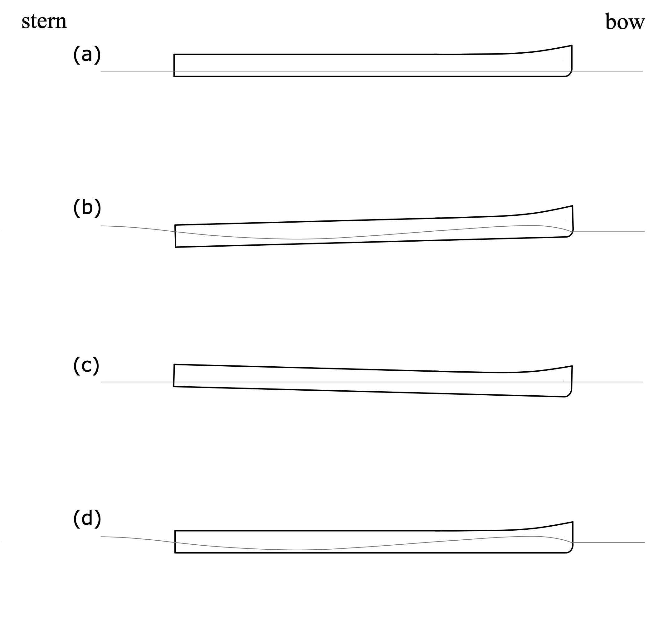
Figure 1: Static and dynamic trim.
In Fig. 1(a) the hull is trimmed level in quiescent water. When underway at its hull speed a bow wave and sternward trough form alongside the hull. As we learned in Part 4, when water moves past the hull it is slowed by the bow. Adopting a paddler-centric coordinate system, the kinetic (motion) energy of the inflow must therefore decrease at the bow. Since energy is conserved, the flow’s energy there is transformed into potential energy in the form of a bow wave. And because the water accelerates as it passes the hull the kinetic energy downstream of the bow increases, which means the potential energy decreases. This results in the trough alongside the hull as shown in Fig. 1(b). The combination of a bow wave and sternward trough causes the bow to rise. This occurs because the hull is buoyant – remember Archimedes’ Principle? – and inclines itself so as to match in an average sense the new inclined “waterline” drawn from the bow wave to the sternward trough. The hull in Fig. 1(b) therefore has a “bow up” dynamic trim.
In Fig. 1(c.) the hull is trimmed bow down in quiescent water. When underway the bow still rises, and the stern still sinks. But since the hull had a bow down static trim angle, once underway the bow down trim becomes a level dynamic trim, as shown in Fig. 1(d). This assumes of course that we picked the correct static trim angle to exactly offset the change in trim once underway. Since hulls are designed to be most efficient with a neutral dynamic trim it behooves you to experiment with fore-to-aft weight distribution to find this trim point. And then vary it depending on conditions: very shallow water entails a larger bow wave, requiring a more aggressive bow-down static trim to keep the hull level and not “climbing a hill” on shallow water waves.
Trim also impacts a hull’s handling in yaw, e.g., rotation when view from above. Consider the three trim scenarios depicted in Fig. 2: level, bow down, and bow light (or stern heavy, if you prefer).
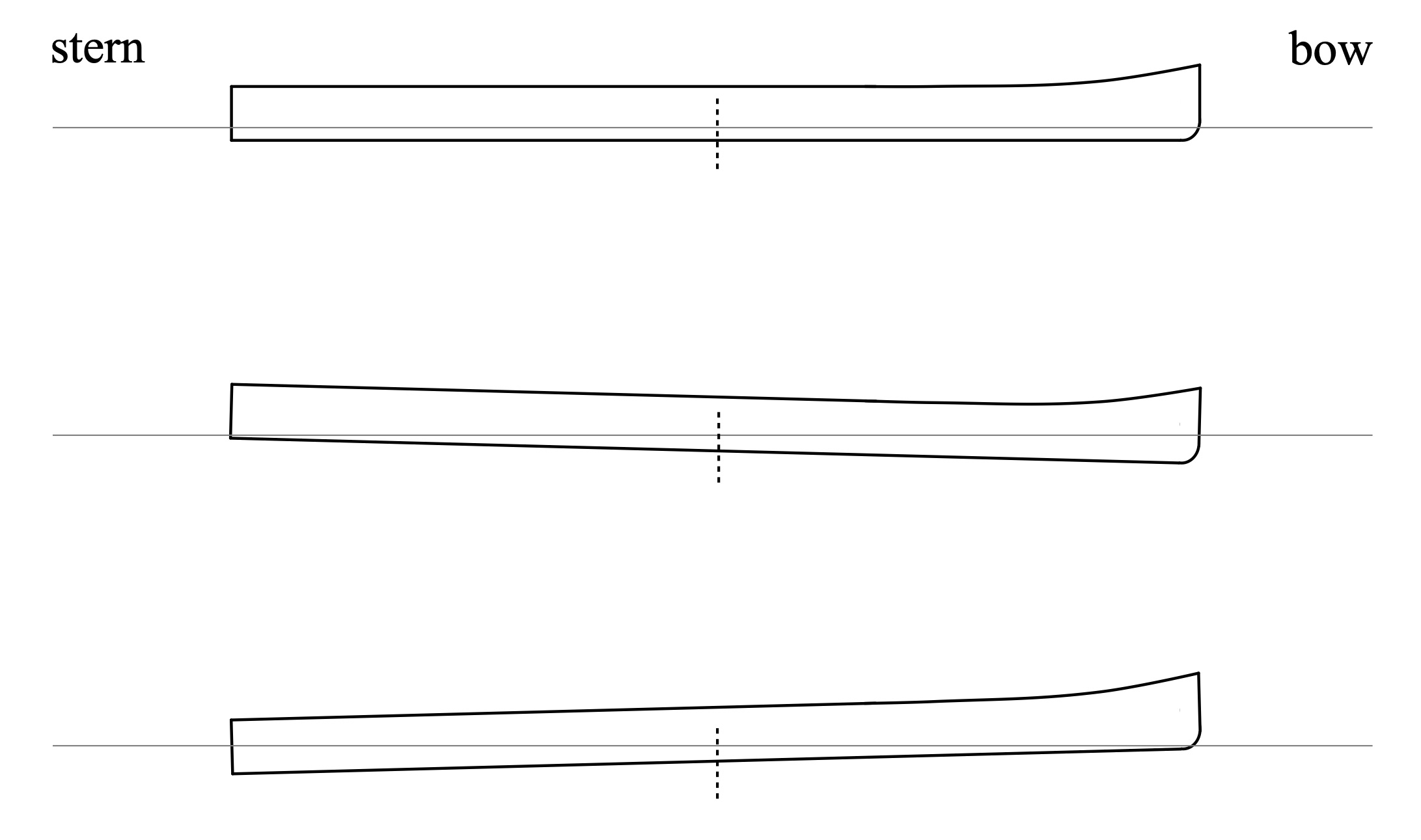
Figure 2: Three states of trim, hull without rocker.
Experientially, many if not most readers will know that a bow down trim “lightens” the stern and makes it easier to follow a line on a twisty river when running upstream. Or that a bow light trim helps in current when back-paddling in order to “set” a hull to a particular cross-river location. If you trim bow down and encounter a beam wind the hull will turn into the wind, while a bow light trim causes the hull to turn away from the wind. We all know this to be true. But why is it true?
We’ll start with a simple experiment that you can do right now, while you’re reading this article. From Part 26:
“Straighten your arm out in front of you, with your hand flat and parallel to the floor. Now briskly move your hand side-to-side, arm straight, and notice the sensations of air passing it.
“Next, repeat this experiment with your hand still flat, but now held vertically (e.g., perpendicular to the floor), briskly moving your hand side-to-side, arm straight. Notice anything different? Do you feel more force distributed over your palm in this orientation than before?”
This simple experiment is even more dramatic if done by sticking your hand in the water alongside a moving hull. With your hand aligned to the flow the water rushes past it. With your hand held perpendicular to the flow the amount of force on your hand can be quite large.
You can extend this experience from hands to hulls. Why does it take less paddle force to move a hull forward compared to drawing it sideways? If you said “friction,” note that the friction drag force is proportional to the hull’s wetted surface area – see The Drag Equation in Part 26. The wetted area doesn’t change whether you paddle it forward, draw it sideways, or anything in between. While friction drag is present, there’s something else going on: form drag.
Form drag arises because objects in flow generate a wake, causing the flow’s momentum to change. This occurs merely because the object is present in the flow, or the object is moving in still water. Recall changes in momentum give rise to force due to Newton’s 2nd Law. And the drag force is proportional to the cross-section area of the wake, which is proportional to the cross-section area of the object.
Returning then to Fig. 2, note the vertical dotted line amidships in each trim scenario. For level trim the below-waterline hull cross-section viewed from the side is pretty much equal for the front half of the hull and the back half. For bow down trim the below-waterline cross-section of the front half is greater than the back half. This means the submerged forward half of the hull has greater form drag than the back half. If we think of drag as resistance to movement, then bow down trim implies that the bow will resist side-to-side movement more than the stern because of its greater form drag. For bow light trim the submerged back half of the hull has greater form drag than the front half. This implies that the stern will resist side-to-side movement more than the bow because of its greater drag.
A rockered hull’s side-on form drag is similar, but the effect is not as dramatic compared to a straight-keeled hull. You can see why in Fig. 3 for a symmetric hull. A rockered hull has less volume in the water toward the stems (e.g., the ends of the hull) and more in the belly. When a rockered hull is trimmed bow down, the difference in side-on submerged cross-section area, front half to back half, is less than for a straight hull. The greater the degree of rocker, the lesser the difference.[2]
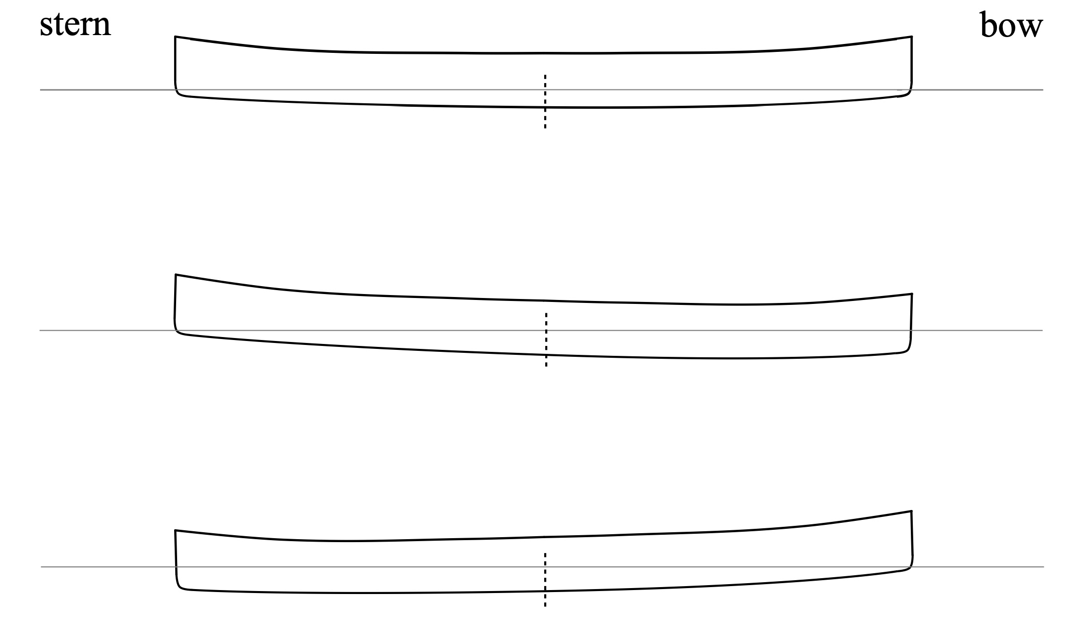
Figure 3: Three states of trim, hull with rocker.
We might be tempted to conclude that the deeper end of the hull acts like a rudder. This isn’t the case. A rudder rotates to deflect incoming flow and generate lift much like an airplane wing, thus pulling the stern of a rudder-equipped vessel to one side or the other. This rudder-induced lift force induces a torque about the hull’s center of rotation, and the hull turns. Unless our hulls bend,[3] submerged ends of the hull don’t rotate to deflect flow. Instead, the submerged end acts more like a pivot. Not a fixed pivot like a hinge, but the deeper end of the hull resists side-to-side motion in comparison to the shallower end.[4]
If the hull is underway with a bow down dynamic trim, the bow “pivot point” will keep the hull aligned with the flow. If instead the hull has a bow light dynamic trim the bow may feel soft, the boat may track poorly, and can become susceptible to current-induced yaw. This is a bit like a pendulum in two different configurations, as illustrated in Fig. 4.[5]
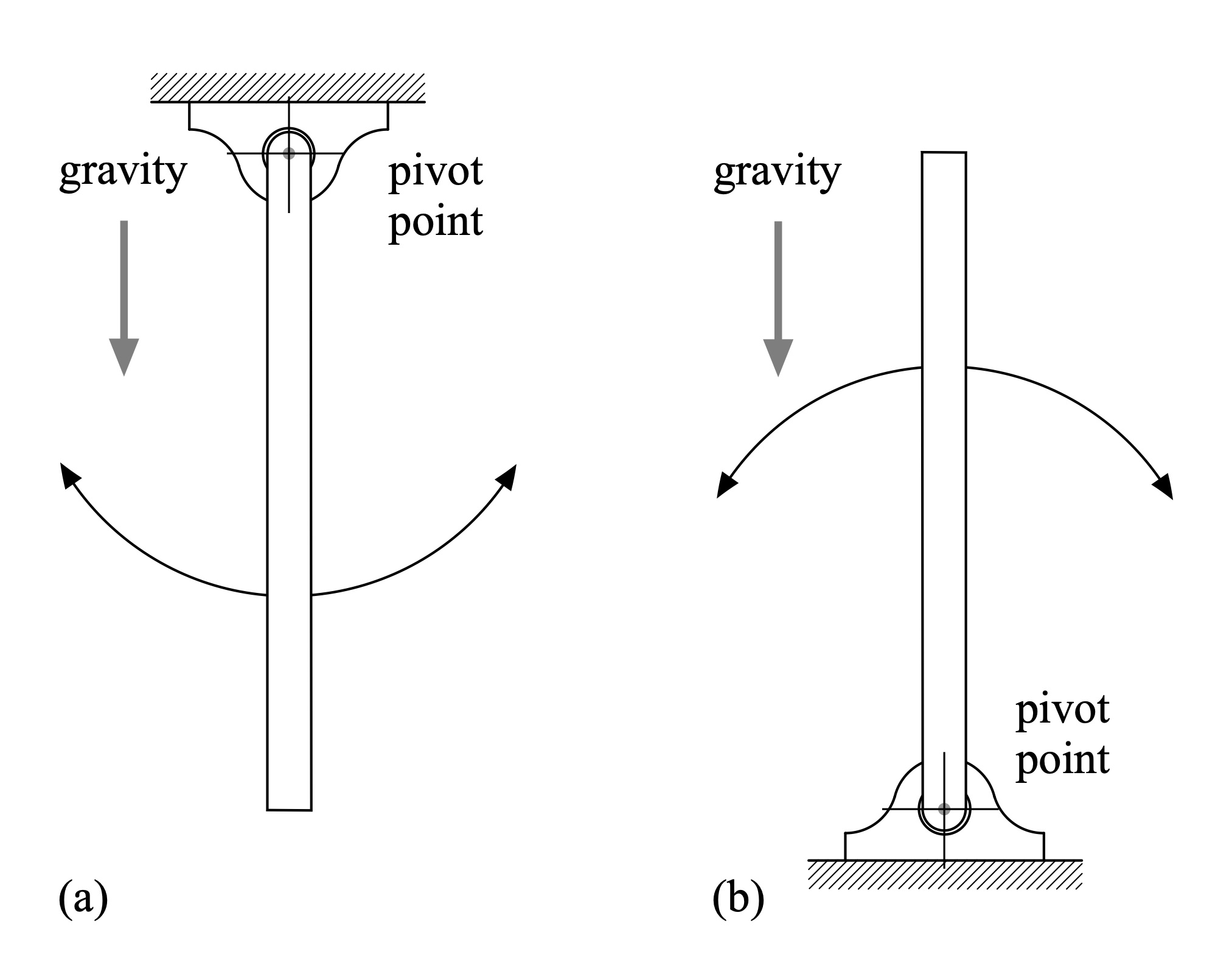
Figure 4: Unstable and stable pivot locations.
When a hull is underway the incoming flow pushes against the hull. If the hull is trimmed bow down this is somewhat analogous to a pendulum hanging in a gravity field, as depicted in Fig. 4(a). The acceleration of gravity[6] induces a force that pulls on the pendulum, acting as a restoring force to align the pendulum with the gravity field when it is deflected to either side. This configuration is stable because the pivot point is at the top of the pendulum: the force induced by gravity acts through the pendulum’s center of mass, which is below the pivot. A hull will behave similarly, to a point – unlike the pendulum, a hull’s pivot can also translate side-to-side. Setting an angle this way is a nice way to cross a whitewater river.
By contrast, Fig. 4(b) depicts the same pendulum in a gravity field, but now with the pivot point at the bottom. This is analogous to a hull underway into incoming flow with a bow light trim. Gravity again induces a force that pulls on the pendulum through its center of mass, which is now above the pivot. The pendulum is only aligned with the gravity field when it is perfectly balanced on the pivot. Consequently, this configuration is unstable.
If you’ve ever tried to balance a pencil on your fingertip you are familiar with this inverted pendulum problem. The pencil can be stabilized, but it requires continuous adjustment.[7] Similarly, a hull that is bow light with its “pivot” astern, moving through an incoming flow, can be “destabilized” and knocked off a straight course without introducing corrective paddling strokes. In strong current this effect can be rather dramatic, and remarkably quick. But for a skilled whitewater paddler this slight trim-induced instability can be used advantageously for quick maneuvering.[8] Or, wilderness paddlers who are working a loaded boat down rapids will use a bow-light trim while back-ferrying to move across a current and avoid downstream obstacles.
LEAN
In addition to trim, a hull’s lean impacts handling. Skilled SUP paddlers move all over their boards to carve turns and spin their craft; they are both inducing lean and significantly changing the mass distribution of the combined board / paddler system to create pivots and new moments of inertia. In what follows we’ll restrict ourselves to some basic hydrodynamics of leaned hulls, but keep in mind the role of changing a hull’s mass distribution as well.
Consider an unrockered hull in a uniform flow[9] with streamlines as shown in Fig. 5. Because the hull is symmetric side-to-side the streamlines are symmetric across the hull as well.
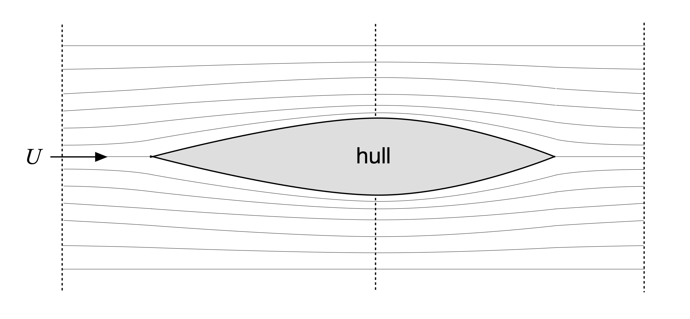
Figure 5: Hull and inviscid streamlines.
In Part 26 we learned that the kinetic (motion) energy of the incoming flow increases at the location of the hull’s maximum width. This location is indicated by the vertical dotted line in Fig. 5. Increased flow speed means that the kinetic energy. Because the overall system’s energy is conserved, this increased kinetic energy requires that the potential energy at this location must be less than that at the bow or stern. For fluids, potential energy entails a change in pressure. Thus the flow’s pressure at the hull’s maximum width is less than at the bow or stern; the pressure varies along the hull’s length in proportion to the changes in flow speed at each location.
Since the hull is symmetric side-to-side the pressure changes are also symmetric side-to-side. Consequently, the pressure-induced forces induced along the port and starboard sides of the hull cancel each other out. With no net cross-wise force the hull doesn’t accelerate abeam, in concordance with Newton’s 2nd Law of motion, which requires that unbalanced forces induce acceleration in inertial bodies (like a hull).
What if the hull were asymmetric below the waterline? Consider the following model problem: flow past a hemispherical rod, as shown in Fig. 6. An object with a hemispherical shape is asymmetric top-to-bottom to this inflow. The streamlines in Fig. 6 move from left-to-right. Red dots are shown in one streamline below the rod, and in one streamline above. Initially, these dots are parallel to each other and uniformly spaced in the streamwise direction before encountering the rod. As the flow moves past the lower half of the rod these streamline markers retain their uniform spacing; the flow speed is unchanged. Since for inviscid flow these points must rejoin downstream of the rod, the markers must spread out over the curved top half of the rod, reflecting the increased speed and thus increased kinetic energy of the flow there. This increased kinetic energy necessitates a decrease in potential energy due to energy conservation, hence the pressure along the curved half of the cylinder is less than along the flat half. This imbalance of forces gives rise to a net lift force on the rod, as indicated in the figure. And since imbalanced forces induce acceleration in inertial bodies due to Newton’s 2nd Law, this flow will cause the cylinder to move in the direction of the lift force. This is in part how airplane wings work.
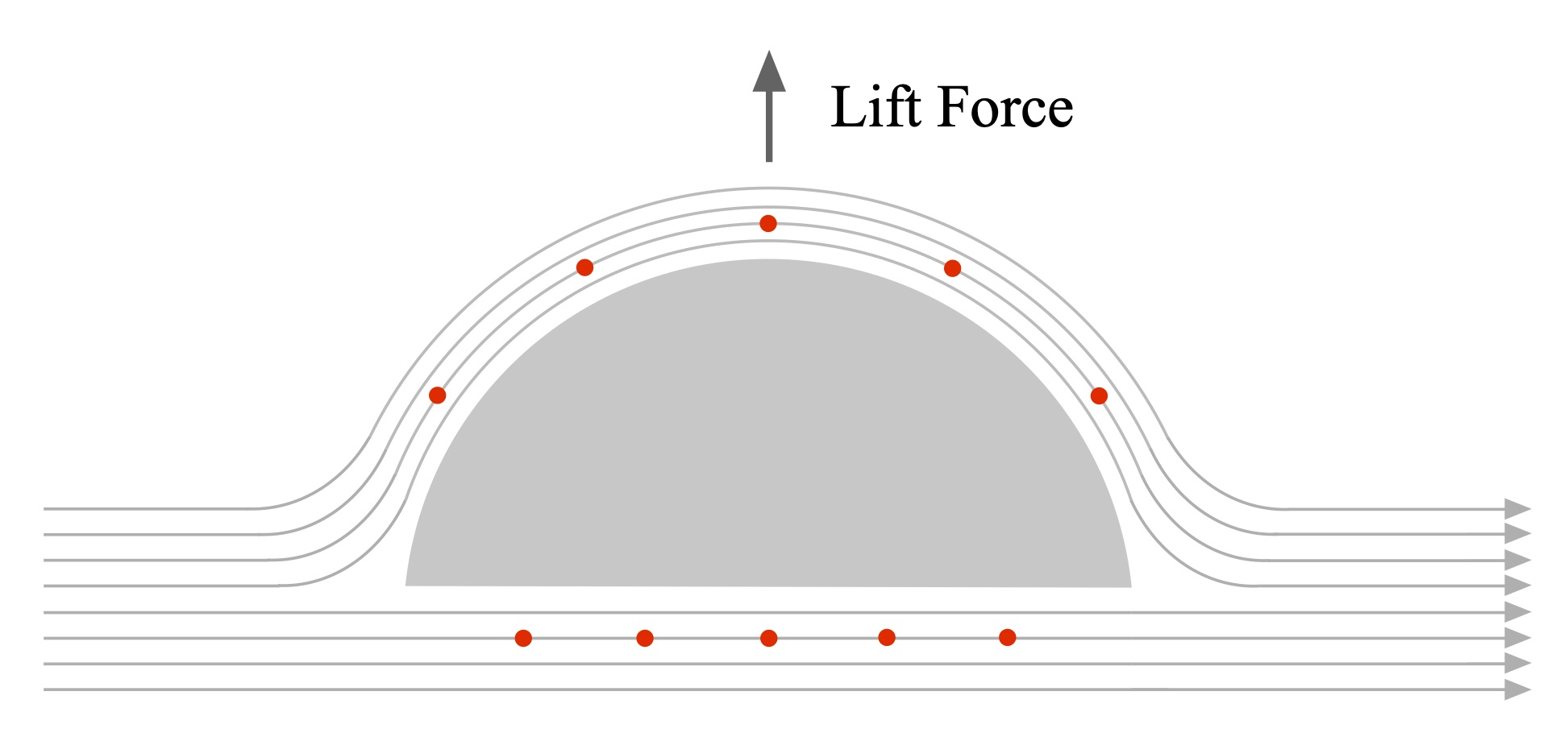
Figure 6: Hemispherical section and inviscid streamlines.
When we lean a hull to one side, its shape below the waterline becomes asymmetric. This is illustrated in Fig. 7 for the hull of Fig. 5 over three amounts of lean. As the hull is progressively leaned, we expect the net beam-wise force F to increase as well due to the increasing asymmetry, as suggested in the figure.
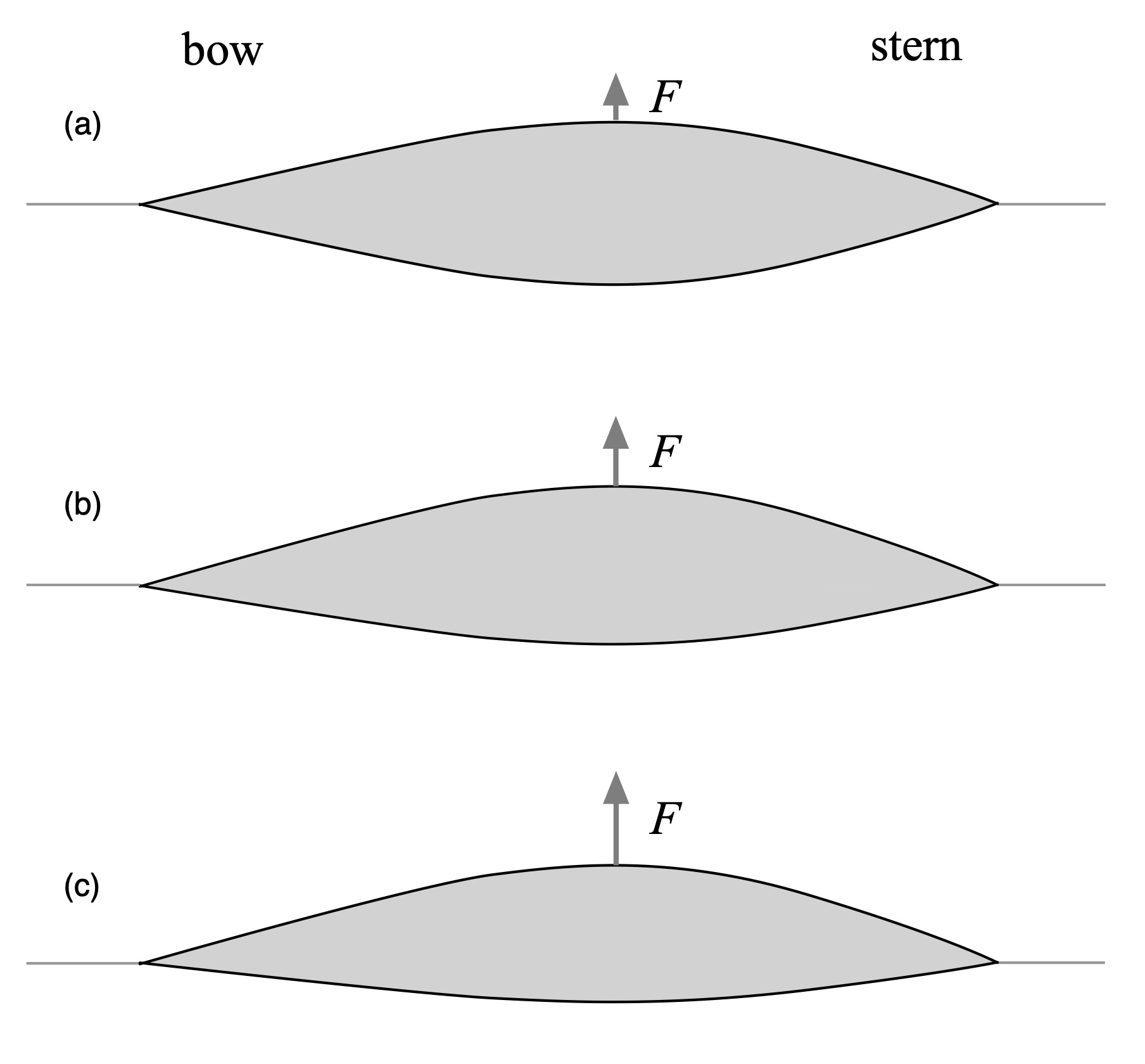
Figure 7: Waterline shape for various leans, plan view, unrockered hull.
If the hull has a bow or stern pivot owing to trim, this unbalanced force, acting through the hull’s center of mass, will cause the hull to rotate about the pivot. This is why one leans a hull to the outside to carve a bow-down turn; the hull will skid toward the leaned side owing to the sideways force and the lightened stern. Add in a brisk forward stroke or a sweep on the leaned side and you’re off. Note that the cross-wise unbalanced force does not itself turn the hull. Rather, if the pivot location is offset from the force’s point of action this creates a torque, which results in rotation. If they are coincident, the hull side-slips.
A leaned hull also presents an asymmetric head-on profile to the flow, as shown in Fig. 8 for various amounts of lean. Not only is there an outward-directed unbalanced force due to the asymmetry, but the form drag of the hull becomes asymmetric as well, just like we discussed in relation to front-to-back trim. With greater form drag on the deeper side this creates a kind of “outside pivot” that further encourages the leaned hull to spin. An outside lean and a bow-down trim reinforce each other’s induced form drag.
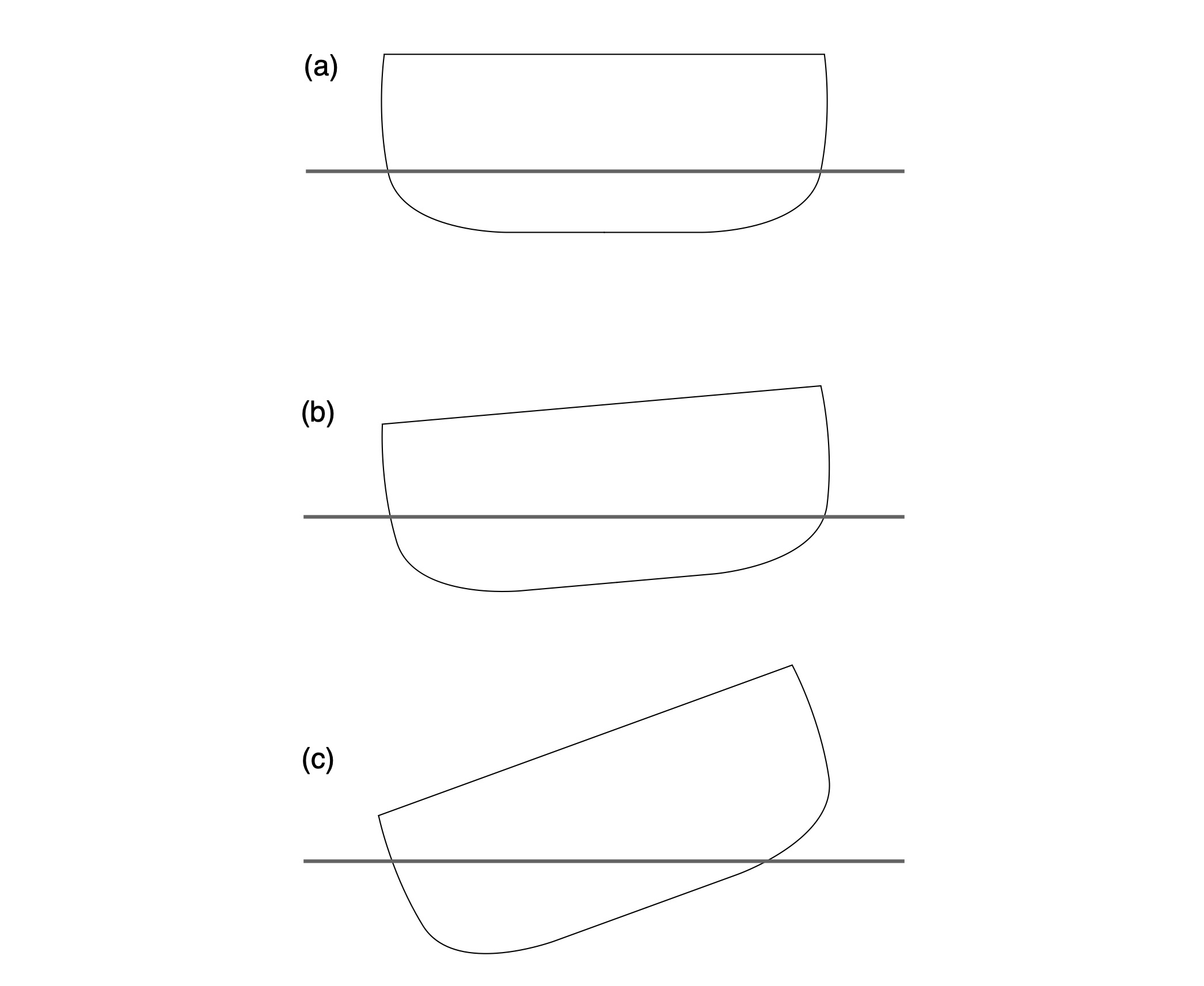
Figure 8: Various hull leans, front view.
SUMMARY
In this installment of the Science of Paddling series we’ve looked at trim in light of form drag and inviscid pressure forces due to hull asymmetries below the waterline. Trimming down a portion of the hull creates a kind of pivot point around which the hull can be turned. Combing a bow-down trim with an outside lean creates both a forward pivot as well as outward-directed forces to help a hull carve turns. The analysis is broadly applicable across a range of hulls and paddling styles.
There is of course more to the story than just localized form drag and induced lift – the flow around a hull is complex to start with, and becomes more complex with changing trim. Plus there is turbulence, eddies, and the like. But these concepts, grounded in physics, will nonetheless help you understand what is going on with your hull in most conditions.
Bummer that we didn’t get to use any calculus. But in a way this is the goal of the Science of Paddling series: to foster insight that can be applied to you and your hull, grounded in the details of science.
v1.0
© 2021, Shawn Burke, all rights reserved. See Terms of Use for more information.
- For a hull with asymmetric rocker, best to call the hull’s manufacturer! ↑
- I must emphasize that the effect is still present in a rockered hull, just a bit less. If the submerged rocker’s shape was perfectly circular (and the hull had a uniform cross-section bow to stern) the effect would disappear – but that would make for a fairly strange hull. ↑
- Which sometimes happens, but usually when it wraps around a fixed obstacle and breaks. ↑
- And the fixed end of a hinge’s pivot certainly resists motion. ↑
- Note that a hull’s pivot point is not fixed like the bearing shown in Fig. 4; this is an analogy. ↑
- Yes, gravity is an acceleration. We experience it via the force it induces in objects that have mass, like our weight. ↑
- This inverted pendulum models the feedback control problem central to first stage booster rocket flight. ↑
- Another analogy: modern high-performance jet aircraft are inherently unstable, and are only made stable through the use of feedback flight control systems. Yet this instability can be used to make exceedingly quick climbs and turns, faster than a more stable airframe is capable of, or to produce “decoupled” maneuvers such as flying forward while maintaining upward trim. ↑
- Which, as we’ve often heard, is just a Galilean transformation from an inertial reference frame to a paddler-centric reference frame. ↑