by Shawn Burke, Ph.D.
Introduction
Boat control is mastered by experience. I’ve spent hours training with others, and a major point of emphasis among local racers is boat handling. There is joy to be had in mastering wake riding. Side waking another tandem and maintaining spacing while snaking along a twisty river is absorbing, engaging, and ultimately beneficial to both team’s energy budget.
Another discipline that is emphasizes boat handling is freestyle canoeing. If you haven’t seen freestyle – or better yet, tried it – prepare to be impressed. I’ve been fortunate to see paddlers like Karen Knight, Kim Gass, and Tom MacKenzie spin and slide their hulls with grace and precision. I also took a freestyle course many years ago with Charlie Wilson and only flipped a few times. It sensitized me to noticing the hull’s state, and how forces acting upon it feel.
These disciplines leverage a moment-to-moment understanding of the forces acting on hulls. We want our craft to go from point A to point B, along a certain route or in a particular way, intact and under control. So, in this installment of the Science of Paddling series we’ll draw from the wealth of knowledge in the TSOP vault to develop a compendium of handling scenarios. We’ll consider the forces that support and usurp our control using simple force and moment diagrams. This informs our paddling so we can keep our hulls well behaved in territories both familiar and unfamiliar.
While some of the initial presentation repeats material found in Part 36: Total Drag, the present post stands alone; no need to click back-and-forth. Note that the effects described here are most significant when moving at higher speeds, smaller clearances, significant lean, and/or with hulls that are fuller below the waterline.
We’ll begin once again with a review of Newton’s Laws of Motion.
Newton’s Laws of Motion
In 1687 Newton published his discoveries about forces and their role in the motion of bodies and planets. The most well-known elements of his work are the three Laws of Motion. These axioms describe phenomena we routinely observe in the world around us. More specifically, they describe the forces acting upon a hull. We’ll briefly review the Laws, then apply them to understand each component of force acting on a canoe, kayak, or SUP.
The 1st Law states:[1]
Every body perseveres in its state of being at rest or of moving uniformly straight forward, except insofar as it is compelled to change its state by forces impressed.
We can illustrate the 1st Law using a simple experiment. Consider a person sitting in a rolling office chair atop a hard and smooth floor, as depicted in Fig. 1. If a colleague comes along and gives them a push – a “force impressed” – then the chair and its occupant change their state from being at rest to now moving.
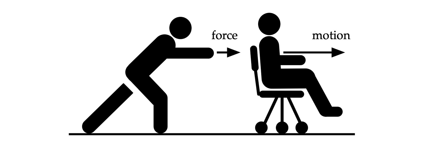
Figure 1: Office chair experiment #1.
Similarly, a hull will remain stationary or move at a constant speed unless an external force is applied. We know that if we increase paddling power, the hull no longer moves at a constant speed – including a “constant speed” of zero – but speeds up instead. The propulsive force from our paddle(s) “compels” our craft to “change its state” from one speed to another.
On quiet water, a hull slows down when stop paddling. This is because drag forces are “impressed” upon the hull, constantly changing its state from one speed to another.
The 2nd Law states:
A change in motion is proportional to the motive force impressed and takes place along the straight line in which that force is impressed.
In the 2nd Law, motion means momentum, the product of an object’s mass and velocity. Consequently, a change in an applied force, such as that delivered by a paddle, changes the momentum of the hull system in the direction opposite the paddle’s action. The 2nd Law also helps us understand form drag, which we’ll revisit below.
An interesting consequence of Newton’s 2nd Law is that the total momentum of a system is constant. For example, if I sit in a chair with well-oiled casters atop a smooth tile floor, and throw a heavy object away from me, I’ll end up moving in the opposite direction. This is illustrated in Fig. 2.
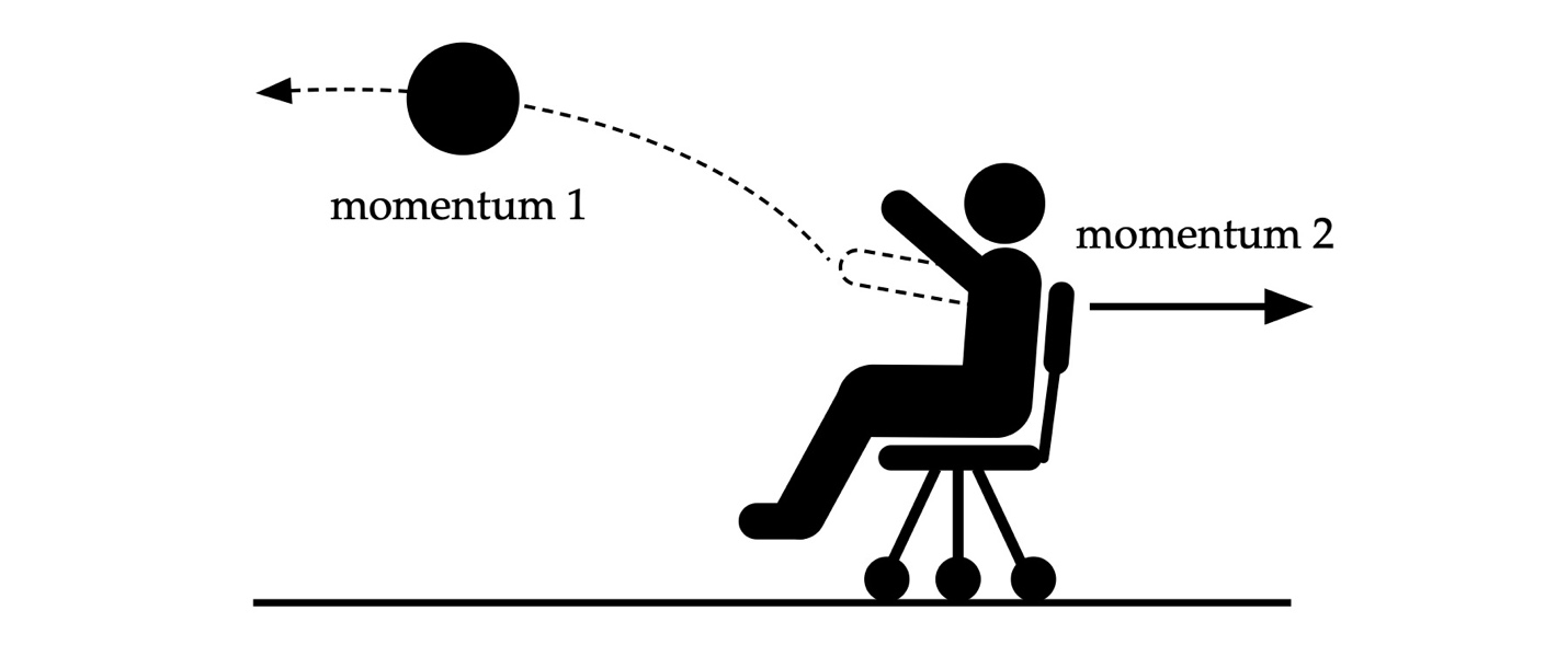
Figure 2: Office chair experiment #2.
The sum of the momentum of the object and my resulting momentum is constant. For our craft, the paddle converts forces applied through our hands into the momentum of the water it entrains. If the water is propelled astern, then the hull will move in the opposite direction. The craft’s momentum balances the water’s momentum.
The 3rd Law states:
To any action there is always an opposite and equal reaction; in other words, the actions of two bodies upon each other are always equal and always opposite in direction.
Here, “action” means force. The second half of the 3rd Law encompasses orbiting celestial bodies, billiard balls bouncing off each other, and objects in static equilibrium. For example, your weight is a force, directed toward the Earth’s center, as illustrated in Fig. 3. If the chair didn’t provide a reaction force to your weight, then you’d fall through to the floor, accelerating from the force imbalance owing to Newton’s 2nd Law. Ditto for standing on the floor.
![]()
Figure 3: Forces and their reactions.
The 3rd Law also applies to rotational motion. Consider the pivot and beam depicted in Fig. 4. This is much like the teeter-totters played we on as kids.
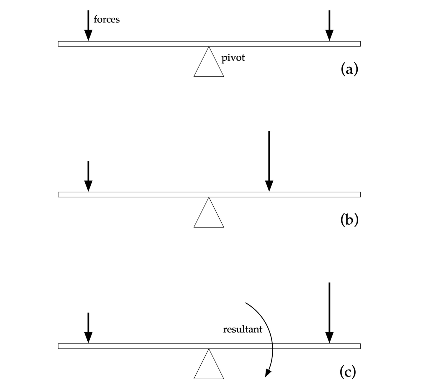
Figure 4: Moment arm and forces.
In Fig. 4(a) the two forces of equal magnitude act downward. Since they are equidistant from the pivot point the beam remains horizontal. In Fig. 4(b) a smaller force presses down at the beam’s left end, while a larger force presses down at a shorter distance from the pivot. Since the product of each force and its respective moment arm are equal here, the beam once again remains horizontal. In Fig. 4(c) the larger force is moved away from the pivot. Now the forces are unbalanced, and the net force causes the beam to rotate in a clockwise direction around the pivot. We’ll rely on this type of 3rd Law analysis to model handling in various scenarios.
In what follows we’ll also rely on a later discovery to Newton’s Laws, attributed to James Prescott Joule: conservation of energy. Joule found that mechanical, electrical, and heat energy are fundamentally the same thing in different forms. While energy can be exchanged within a system over time, the system’s total energy remains constant. This will help us understand wave drag.
The Forces on a Hull
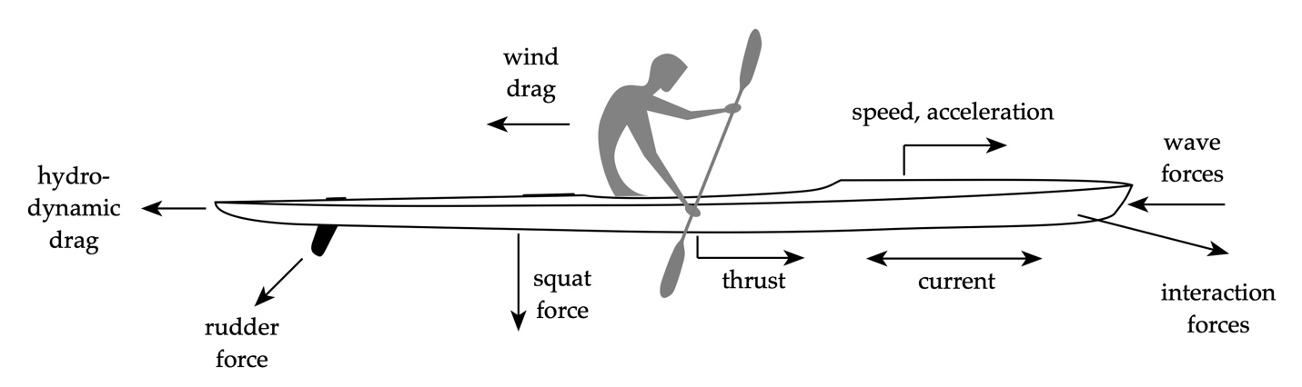
Figure 5: Paddle, hull and various forces.
Consider the hull depicted in Fig. 5. Various forces are “impressed” upon it. The combination of these forces are balanced when the hull is either stationary or moving at a constant speed owing to Newton’s 3rd Law.
- The paddle increases the momentum of the incoming water, providing a propulsive force due to Newton’s 2nd Law. Changes in the propulsive force change our hull’s momentum, speeding it up or slowing it down because of Newton’s 2nd Law.
- A wind-induced drag force acts on the hull above the waterline, and on our paddling, slowing them down (“changes the state”) because of Newton’s 1st and 2nd Laws.
- Waves impinge on the hull at various angles and periods, imposing dynamic pressure forces on the hull that act owing to Newton’s 1st and 2nd Laws.
- A squat force arises when traveling in shallow water that arises due to Newton’s 2nd Law.
- Interaction forces with other hulls, docks, and shoals arise due to flow acceleration between the hull and these objects.
- If our craft has a rudder and it is rotated, it exerts a transverse force owing to the dynamic pressures acting up it, and the lift force it generates.
- And finally, a hydrodynamic drag force slows us down owing to Newton’s 1st and 2nd Laws. Hydrodynamic drag comprises friction drag, wave-making drag, and form or pressure drag.
Let’s examine each of these forces and their genesis. We’ll begin with the hydrodynamic drag forces.
Friction Drag
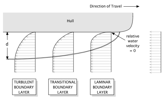
Figure 6: Boundary Layer Development.
The first of the three drag force components is friction drag. Many people think this is the only type of drag acting on a hull. It’s not. But friction drag is the easiest to understand.
As hulls glide over the water, the fluid at the hull’s surface “sticks” there. This phenomena is called the no-slip condition. If we adopt a frame of reference centered in the hull, the water appears to move past us at our hull speed. Let’s call that speed U. Below the waterline, the relative speed between the hull and water must equal zero at the hull’s surface. Consequently, there must be a transition region for the water to “catch up” with the free-stream speed U. This region is called the boundary layer, illustrated in Fig. 6.
Immediately adjacent to the hull’s surface, the physics is dominated by diffusion owing to shear stresses, e.g., friction. This holds true across the laminar portion of the boundary layer. As you move further away from the hull, and along the hull’s length, the boundary layer is dominated by vortex generation – turbulence. These energetic processes are the genesis of friction drag. And they are fed by the engine’s power because the hull is moving through a fluid. The total system energy is conserved within the control volume encompassing the hull and the boundary layer. Friction drag is merely transforming energy from motion into the boundary layer, slowing you down.
Wave Drag
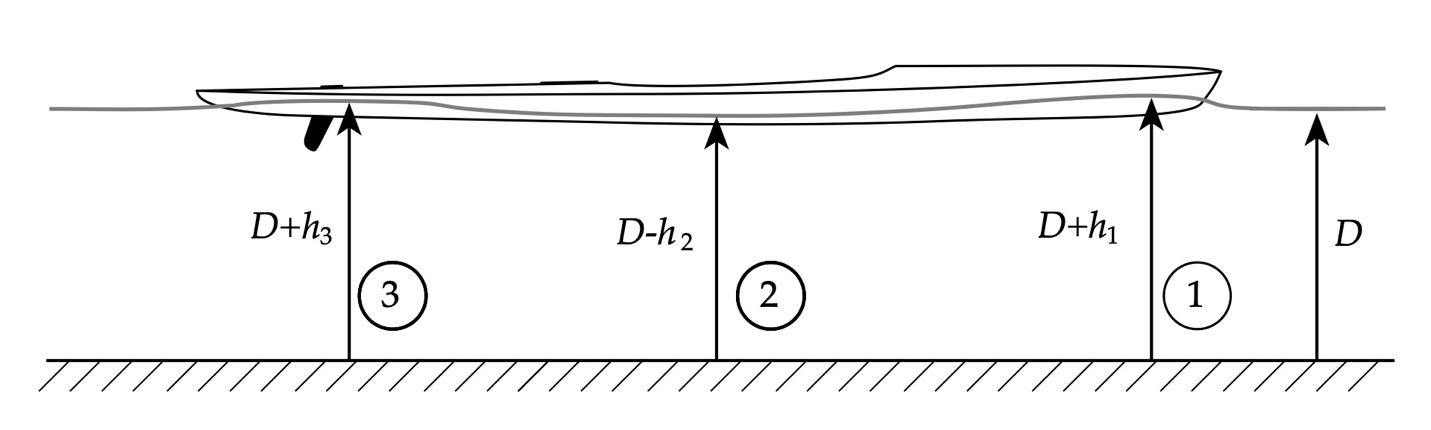
Figure 7: Wave generation alongside a hull.
The second of the three drag force components is wave drag. Wave drag arises because of the change in the water’s kinetic energy as it encounters the hull. This is illustrated in Fig. 7.
We’ll assume once again that our hull is moving at speed U. If we adopt a hull-centered frame of reference, then from our perspective the water is flowing toward our hull at the speed U. When the water first strikes the hull at the bow, it immediately slows down, as if its kinetic energy hit a solid object – which it did. The water piles up near the bow, rising above the average water depth D as shown in the figure at location ‘1’. This increase in height h1 locally raises the water’s potential energy, much like throwing a ball in the air raises the ball’s potential energy. Since the energy in the hull/water system is conserved, further along the hull the water’s surface must drop below the average depth D by an amount h2, since there is less potential energy there than at location ‘1’ but greater kinetic energy. Depending on the water depth and hull speed the water alongside the hull may create another crest like that shown at location ‘3’.
The wave-like pattern alongside the hull creates waves that radiate outward, as shown in Fig. 8. These waves travel with the craft; the hull acts as an “input” to drive surface waves. Surface waves are a natural phenomenon that are a characteristic of the air/water interface. The character of water waves depends on the water’s depth. In deep water long wavelength waves travel faster than shorter wavelength waves. In shallow water all waves travel in sync, which is why the bow wave “sharpens” and breaks in shallow water.
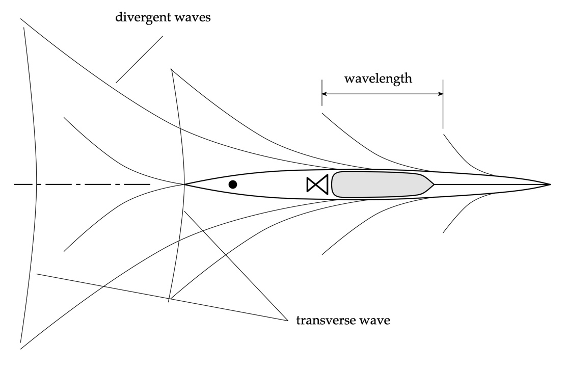
Figure 8: Kelvin-Froude wavetrain propagating from a hull.
We can trace the potential and kinetic energy in the wavetrain to its source: the kinetic energy of the incoming flow. But when we “undo” our coordinate transformation and return to an inertial (Earth-centered) frame of reference, we see that the speed U generating the kinetic energy to feed the waves comes not from the flow but from you. If our hull were not present, there would be no Froude-Kelvin wavetrain. We create it by movement over the water’s surface. And that wave energy continues to radiate outwards as we travel.
The specifics of the wavetrain are also driven by hull design. Some sleek hulls produce comparatively low amplitude waves, while others generate significant transverse waves. But the waves will be there, no matter what. Far enough away from the hull, the wave crests will diverge in a fan-shaped pattern with asymptotes angled 18.6 degrees. Kelvin-Froude waves are a property of the water’s surface; they’re just Nature happening.
The wave shape along the hull leads to variations in the local dynamic pressure, as shown in Fig. 9. The “pillow” of water alongside the bow, and toward the stern in this case, with their higher potential energy, have a higher local pressure than the “trough” of water between them.
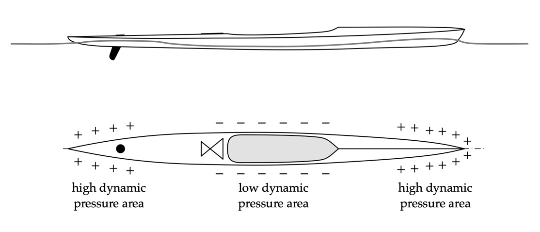
Figure 9: Local pressure forces alongside a hull under way.
As our craft increases in speed the wave pattern along the hull begins to stretch as shown in Fig. 10. At a speed called the hull speed a craft of waterline length L sits within one wavelength
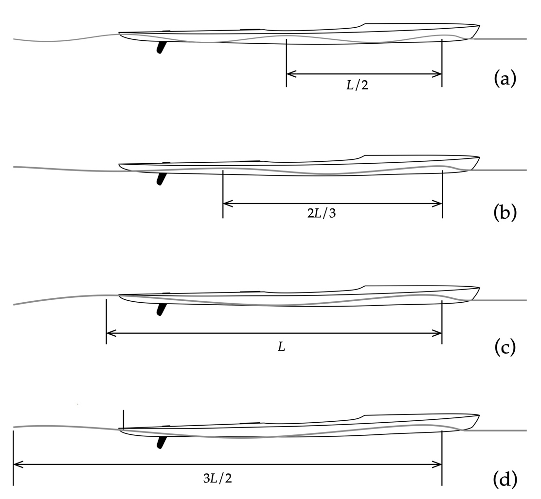
Figure 10: Wave pattern for increasing speed in terms of waterline length.
of the pattern. The hull is proportional to the square root of the waterline length. Above this speed, for most displacement hulls the wave drag grows exponentially. Further, at higher speeds the “trough” alongside the back half of the hull will affect trim, causing the bow to pitch upwards, further impacting hydrodynamic efficiency.
Form Drag
Hold your hand out in front of you, arm fully extended, with the palm held horizontal. Now briskly swing your hand side-to-side while keeping your arm straight. Notice the force exerted on your hand. Next, repeat the experiment, but rotate your hand so the palm is oriented vertically. Notice the force exerted on your hand. The effect is more dramatic if you hold your hand out a car window while driving (just be careful). So why are the forces on your hand different for these two orientations?
Now friction drag is proportional to the hull’s wetted surface area below the waterline. In your “hand as a hull” experiment, the hand was fully immersed in a fluid – air – in both orientations. And the hand’s surface area didn’t change. An analysis based on surface friction alone would predict no change in drag between the two orientations. However, the size and shape of the wake behind your moving hand are different.
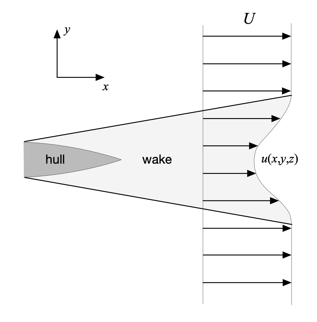
Figure 11: Wake, plan view.
Now consider a hull moving at speed U and its wake as depicted in Fig. 11. We’ll again adopt a reference frame centered on the hull. The wake behind a moving hull reflects a change in the incoming water’s momentum. On average, the flow speed in the wake u is less than the free-stream flow speed U. The wake is highly three-dimensional as well. Consequently, the water, which has mass, has a lower momentum inside the wake than outside it. This change in momentum exerts itself as the form drag force on the hull.
This is a consequence of Newton’s 2nd Law, which reads in part, “[a] change in [momentum] is proportional to the motive force impressed.” The reverse also holds true: a change in momentum impresses a force. You’ve experienced this if you’ve ever ridden in a decelerating car. Decelerating means changing the car’s momentum, which leads to a force that makes you pitch forward in your seat. Here, the change is the difference between the water’s momentum at speed U if no hull were there versus the momentum when the hull is present. Once again, the system’s energy – the fluid’s kinetic or motion energy – is conserved. The energy is redistributed from the unimpeded upstream flow into the wake’s flow, typically including vortices and other fun structures.
Form drag is a property of the wake. The larger the wake, the greater the form drag. This is where apt hull designers earn their keep since the hull shape influences the wake’s size.
Pivot Transfer
When our craft are stationary in still water, or drifting on a steady and uniform current, there are no wave-induced pressure forces acting alongside its hull like those shown in Fig. 9. As a first approximation the hull will naturally turn about its center of gravity CG assuming a neutral trim and neglecting drag differences fore-and-aft from the above- and below-waterline hull shape. This scenario is depicted in Fig. 12.
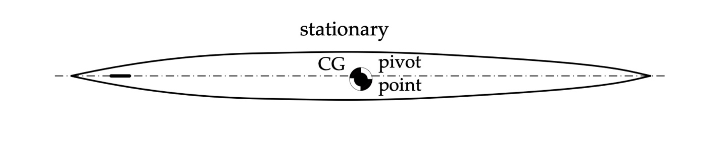
Figure 12: Stationary hull pivot location = its center of gravity.
When the hull is moving ahead in deep water, with the rudder in its neutral position, the various forces acting on it – pressure forces alongside and drag – work to keep the craft aligned with the direction of travel. These act as restoring forces to maintain heading. This is like a pendulum hanging from a pivot like that shown in Fig. 13. The force of gravity, acting through a pendulum’s center of gravity, restores the pendulum to the vertical. The restoring force acts below the pivot point.
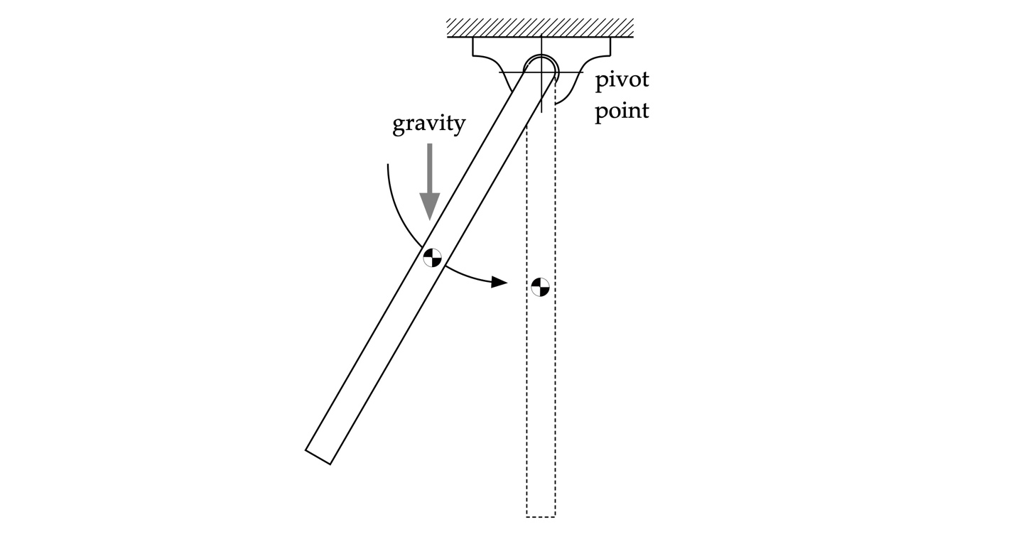
Figure 13: Pendulum in a gravity field.
We see then that the hull forces when moving forward in quiet water are stabilizing; the hull doesn’t spin about its center of gravity. Consequently, we infer that the hull’s pivot point has moved or “transferred” from the center of gravity toward the direction of travel, as show in Fig. 14. The various hull forces on the hull in net act behind the pivot point and are thus stabilizing.
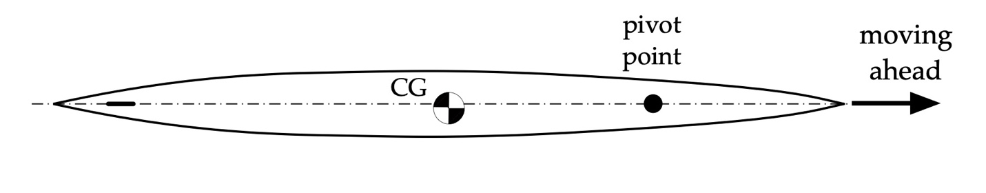
Figure 14: Pivot transfer, moving ahead.
The amount of pivot transfer depends on a hull’s block coefficient. A slender hull’s pivot point will move less than that of a more full-bodied hull. And not surprisingly, the pivot point transfers aft when a craft is moving astern, as depicted in Fig. 15.
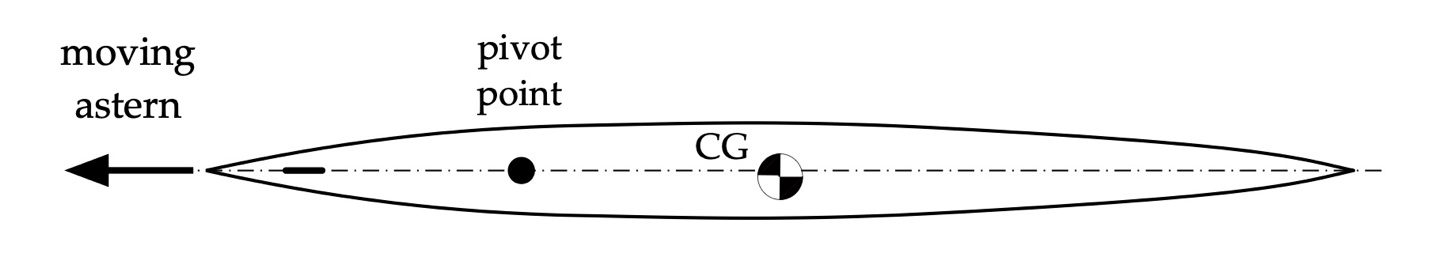
Figure 15: Pivot transfer, moving astern.
Rudders and Force Vectors
Consider the rudder depicted in Fig. 16’s cross-sectional view. This figure depicts streamlines of a fluid flowing from right-to-left that impinges on the rudder.
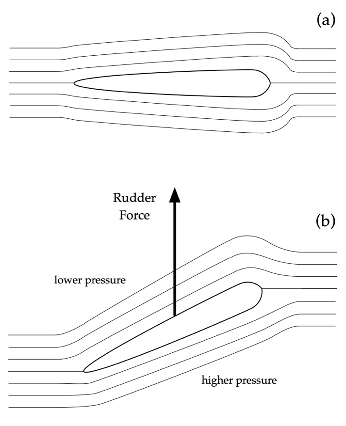
Figure 16: Rudder in cross-section with streamlines.
In Fig. 16(a) the rudder is in a neutral position so that the fluid flows symmetrically over both of its sides. Consequently, there is no imbalance of forces. In Fig. 16(b) the rudder has been rotated. The inflow exerts a higher dynamic pressure on the lower face than the upper. This leads to a force imbalance directed upward as show. There may also be an effect from lift acting in this direction as well. The net pressure forces on the rudder are complex, and the resulting net force in general is directed up and away from the rudder perpendicular to its upper face.
Force has both magnitude and direction, which means force is a vector. Until now we’ve only said forces like the hydrodynamic drag force or thrust act along the direction of motion. In what follows it is usually convenient to use the component of the rudder force, as well as other forces, in a direction perpendicular to the inflow, or to the direction of travel. A force vector and its components are depicted in Fig. 17.
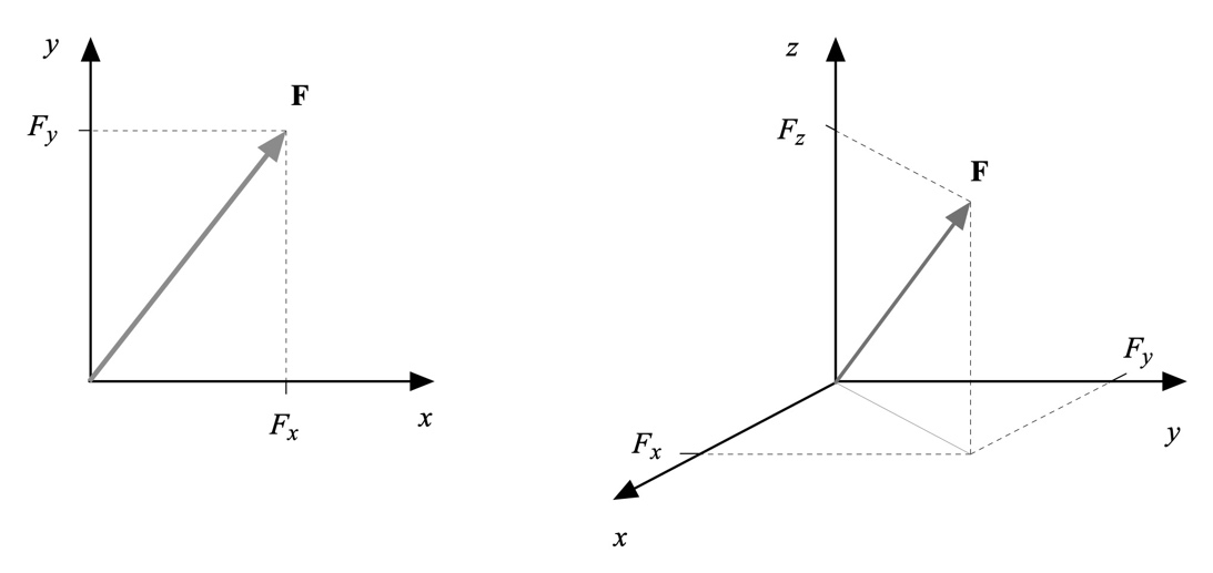
Figure 17: Force vector F and components in perpendicular directions.
Computing the components of a force vector in 2D or 3D requires a bit of trigonometry. For our purposes just remember that force is a vector. While a net force may be acting perpendicular to a hull’s curved surface we’ll typically work with its components in the direction of, or perpendicular to, our motion.
Basic Forces on Our Craft
Now that we’ve considered the sources of several type of forces acting on a hull we can use a moment arm analysis for several common scenarios. First, consider the hull depicted in Fig. 20. The craft is neither moving ahead nor astern. Bow and stern paddlers are drawing the hull to port, or one is performing a draw while the other is doing a pry. This induces a dynamic pressure along the port side proportional to the square of the speed in the that direction. The resultant force, integrated over the hull’s surface, can be idealized as a point force opposing the motion that acts through the center of gravity. We’ve assumed that the pivot point and the center of gravity are coincident in this scenario. The translation of the hull leads to a drag force that opposes motion. This combination of friction, wave-making, and form drag, while acting over the entire hull, is also idealized as a single force directed opposite our motion. If the dynamic pressure and drag forces act to one side or the other of the pivot point this induces a yawing moment. To compensate for this the thrust forces applied fore and aft are adjusted to make the hull translate rather than rotate.
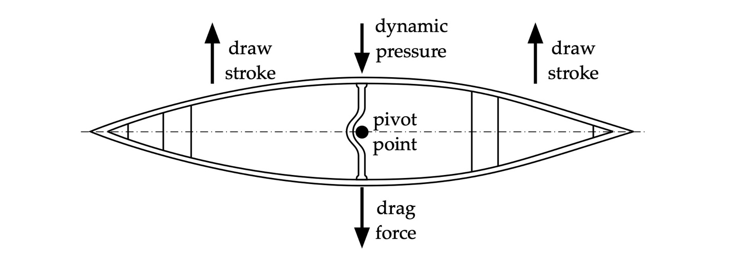
Figure 20: Canoe being translated to port (a “side slip”).
Next, consider the hull depicted in Fig. 21. The craft is neither moving ahead nor astern. Bow and stern paddlers are rotating the hull to starboard by performing draws on opposite sides. This induces a dynamic pressure along the front half of the starboard side proportional to the square of the speed in that direction. The resultant dynamic pressure force, integrated over front half of the hull’s surface, can be idealized as a point force opposing the motion that acts nearer the bow. We’ve assumed that the pivot point and the center of gravity are coincident in this scenario. The rotation of the hull leads to a drag force opposing that motion. The combination of friction, wave-making, and form drag, acting over hull’s front half, is also idealized as a single force directed opposite motion of the boat’s front half. Corresponding dynamic pressure and drag forces arise along the boat’s aft half. The result is a net clockwise turning moment, and the canoe rotates.
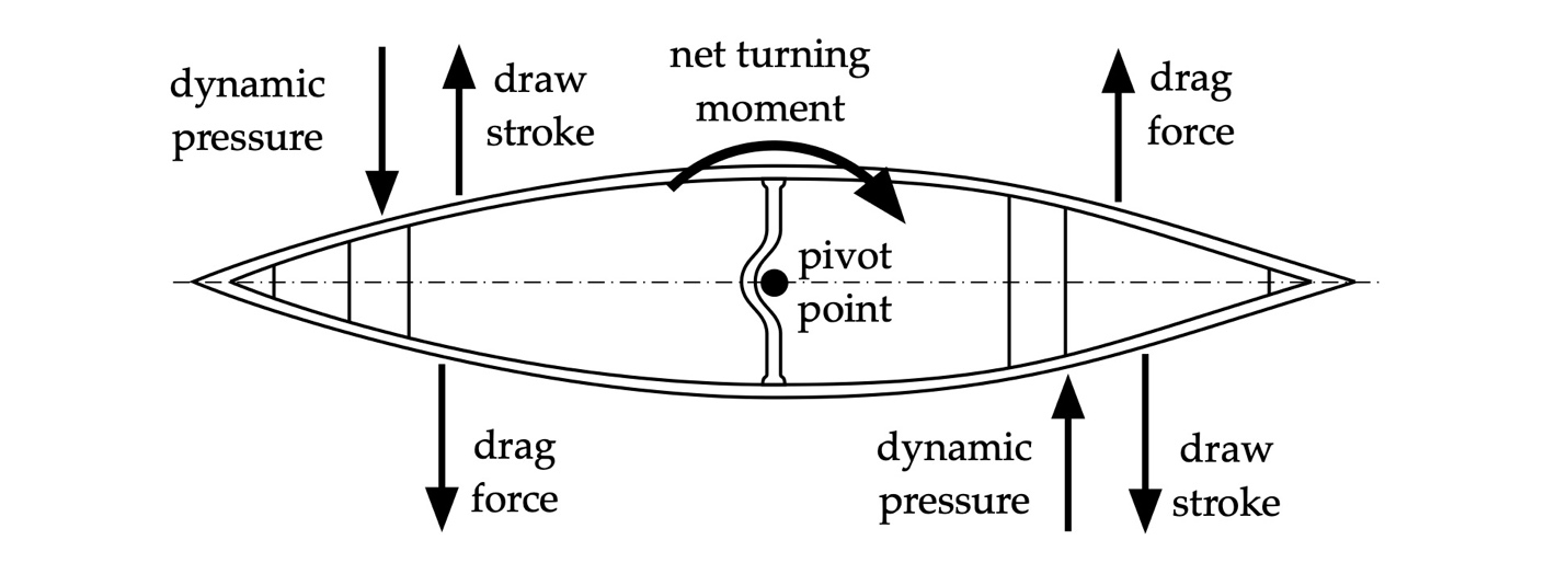
Figure 21: Canoe being rotated to starboard.
Consider now the hull depicted in Fig. 22. The craft is underway ahead. As we discussed above this results in pivot transfer toward the bow, and in the absence of external transverse forces the forces along the hull serve to stabilize its forward motion. Thrust from the paddler must overcome the opposing forces shown to move the craft.
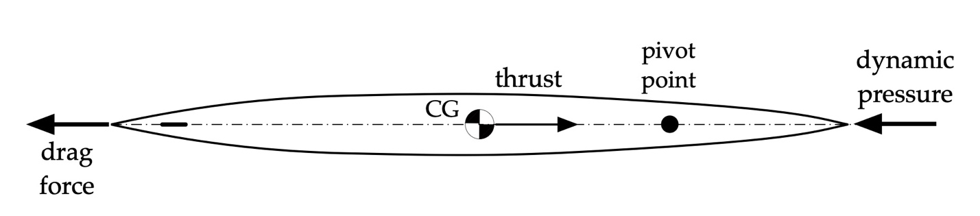
Figure 22: Surfski underway ahead.
Next, consider the hull depicted in Fig. 23. The tandem us underway ahead, with paddlers executing forward strokes on opposite sides. The thrust generated by the stern paddler acts over a longer moment arm from the pivot point than the bow paddler’s. As a result, the hull will slowly yaw to port unless the stern paddler uses corrective strokes like the J-stroke or a pitch.
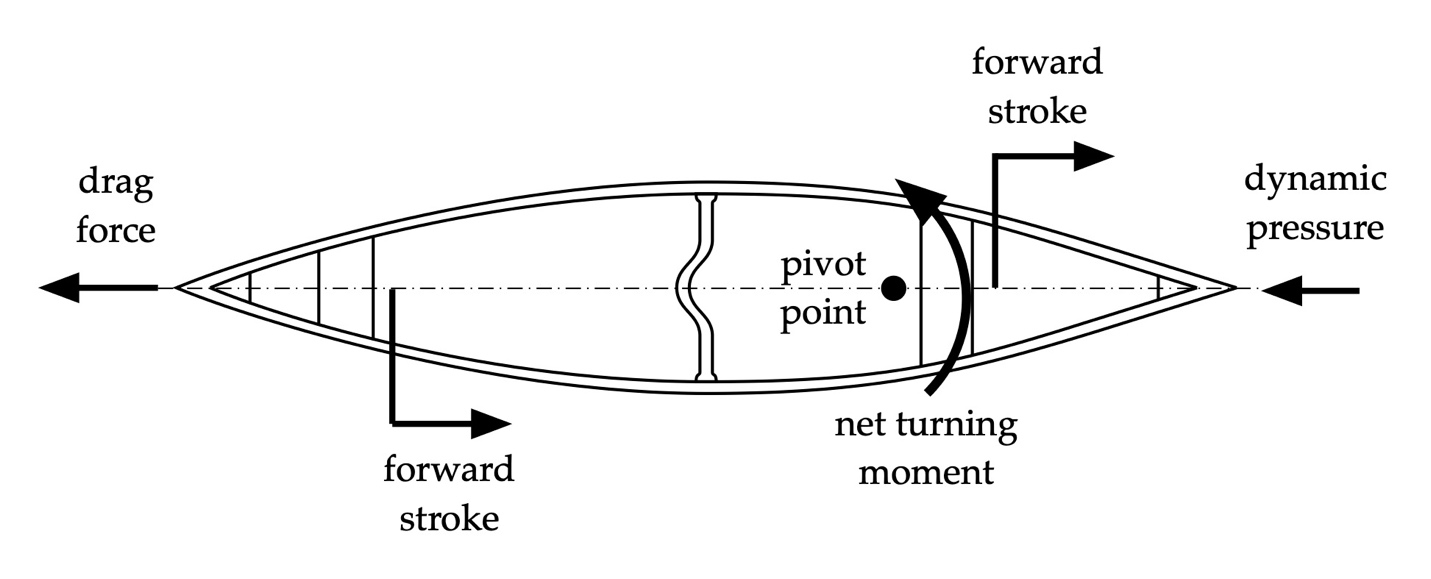
Figure 23: Tandem canoe underway ahead.
Finally, consider the hull with a rudder depicted in Fig. 24. The craft is underway ahead. The rudder has been rotated to induce a transverse force to port. Since the rudder force is astern of the pivot point the resulting moment induces a turn to starboard. As the hull turns the dynamic pressure now results in a force that acts primarily on the bow’s port side. The drag force is shown as a first approximation acting through the center of gravity since it is related to the hull’s wetted area and shape below the waterline.
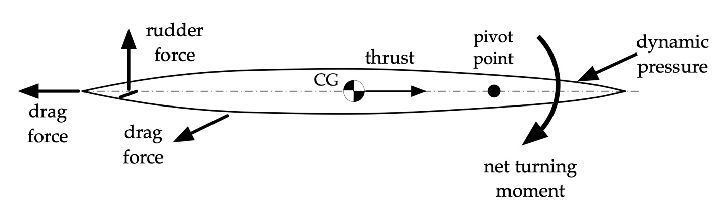
Figure 24: Hull underway ahead and turning to starboard.
Once these forces have balanced, and absent any change in bathymetry that might cause other effects, the hull will carve a turn of constant radius. This is depicted in Fig. 25. The craft’s centerline describes a tangent to the turning circle called the drift angle.
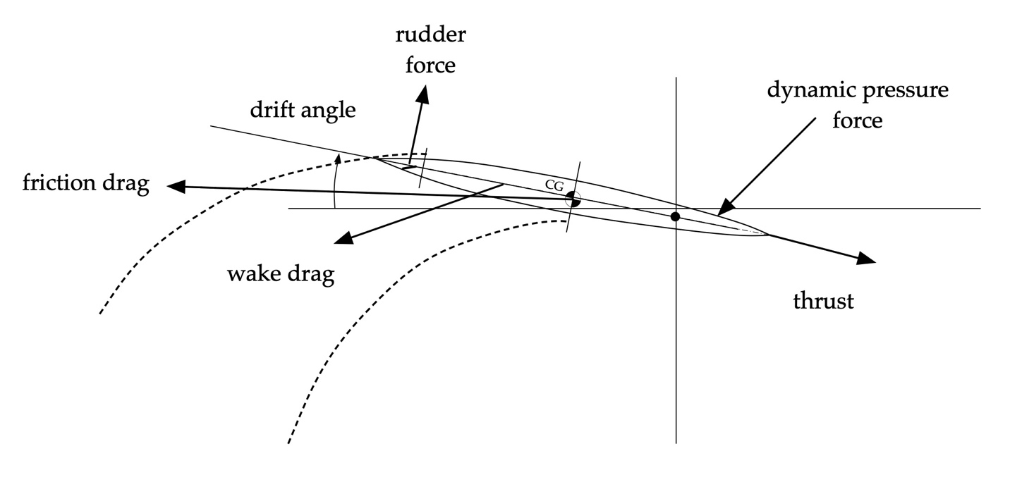
Figure 25: Hull in a turn.
Bernoulli’s Principle
A consequence of Newton’s 2nd Law is that momentum is conserved in a system. Momentum is the product of mass and velocity. So consider now the simple venturi depicted in Fig. 26. For this example, we’ll neglect fluid viscosity.
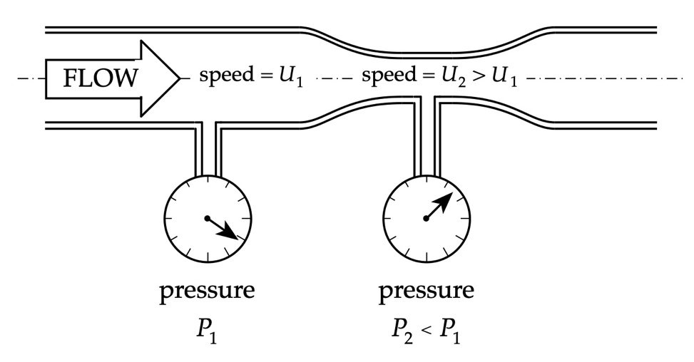
Figure 26: Venturi with pressure indicators.
Fluid flows into the venturi from the left at a uniform speed U1. The momentum of fluid above the first pressure tap is the product of the fluid’s mass and its velocity. The pressure tap there shows a gage pressure of P1. As the fluid passes through the constriction around the second pressure tap it must speed up. This is because of momentum conservation. A smaller plug of fluid in the constriction has less mass. Since the product of its mass and the local velocity U2 must equal the momentum at the first pressure tap, the fluid must speed up within the constriction. If it didn’t the fluid would “pile up” in front of the constriction.
The Bernoulli equation tells us that increasing local flow speed entails decreasing local fluid pressure. Consequently, the pressure P2 at the second tap is less that the pressure P1 at the first. This is the principle of operation used in atomizers, like those seen in old-fashioned perfume spray bottles. We’ll rely on this principle of increasing speed / decreasing pressure in our analysis of interactions below.
Squat
One application of Bernoulli’s Principle is to hull squat. Consider a craft in very shallow water as depicted in Fig. 27.
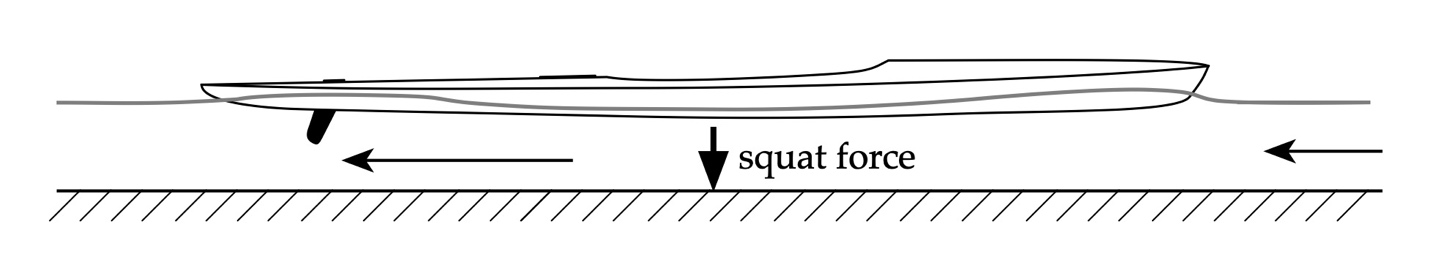
Figure 27: Moving hull in very shallow water.
We’ll adopt a reference frame centered on the boat. From this perspective the water is flowing toward it at a velocity indicted by the upstream arrow. Beneath the hull the flow is constricted, causing the water to speed up there. Consequently, the Bernoulli Principle tells us that the pressure below the hull is less than it is away from it. This reduced pressure causes the craft to be pulled downward via a resultant squat force. Depending on the trim entering shallow water, and the location of the craft’s center of gravity, the squat force may cause the hull to pitch and change its trim. The squat force is inversely proportional to the clearance beneath the hull, and proportional to the square of speed. The effect will be more pronounced in hulls with a fuller cross-section. Note that this force acts in addition to increased wave drag owing to the water’s depth, as discussed in Part 4: Shallow Water.
When crossing onto or away from a shoal the squat force will cause the hull to pitch bow-down or bow-up, as depicted in Fig. 28. The local squat force over the bow or stern still varies inversely as the hull’s clearance, and proportional to the square of speed. Since the suction force acts away from the center of gravity this unbalanced force causes the hull to pitch down at the shallower end. Again, the effect will be more pronounced in hulls with a fuller cross-section.
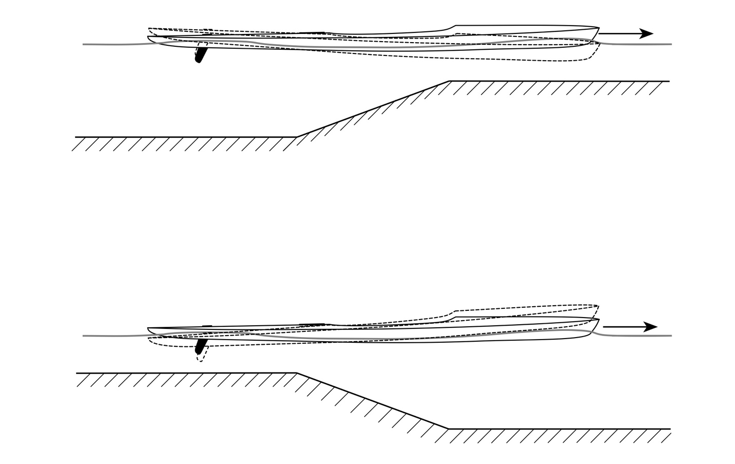
Figure 28: approaching and exiting a shoal (not to scale).
Banks
Consider a hull passing close to a bank, large moored boat, or other fixed structure – which we’ll generically refer to as a “wall” – as depicted in Fig. 29.
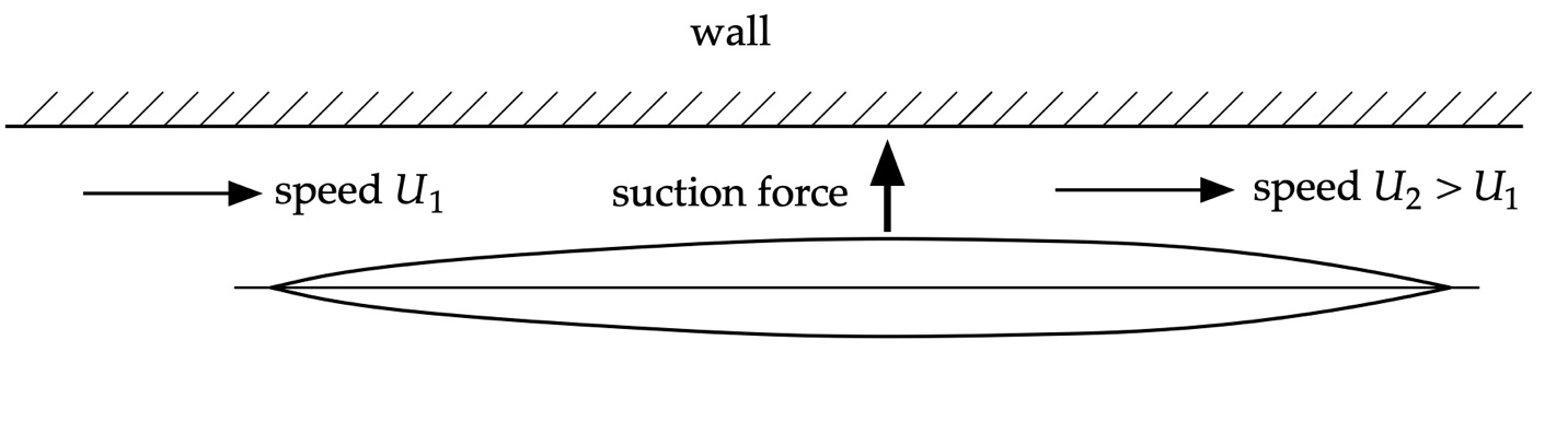
Figure 29: hull and bank.
Once again adopting a hull-centric reference frame, the fluid passing between the hull and wall is constricted. This causes the flow to accelerate to a speed U2 greater than the inflow speed U1. (Alternately, the boat could be anchored in the presence of an oncoming current.) As a result, the pressure between the hull and the wall is less than upstream or downstream, leading to a net suction force that pulls it toward the wall.
The suction force shown in Fig. 29 did not cause the hull to yaw. If, however, the hull is rotated away from the wall the spacing between it and the stern may still create a suction force, as depicted in Fig. 30. Since it is unbalanced about the pivot point this will cause the hull to rotate even more. Without proper attention to rudder position the stern can swing into the wall.
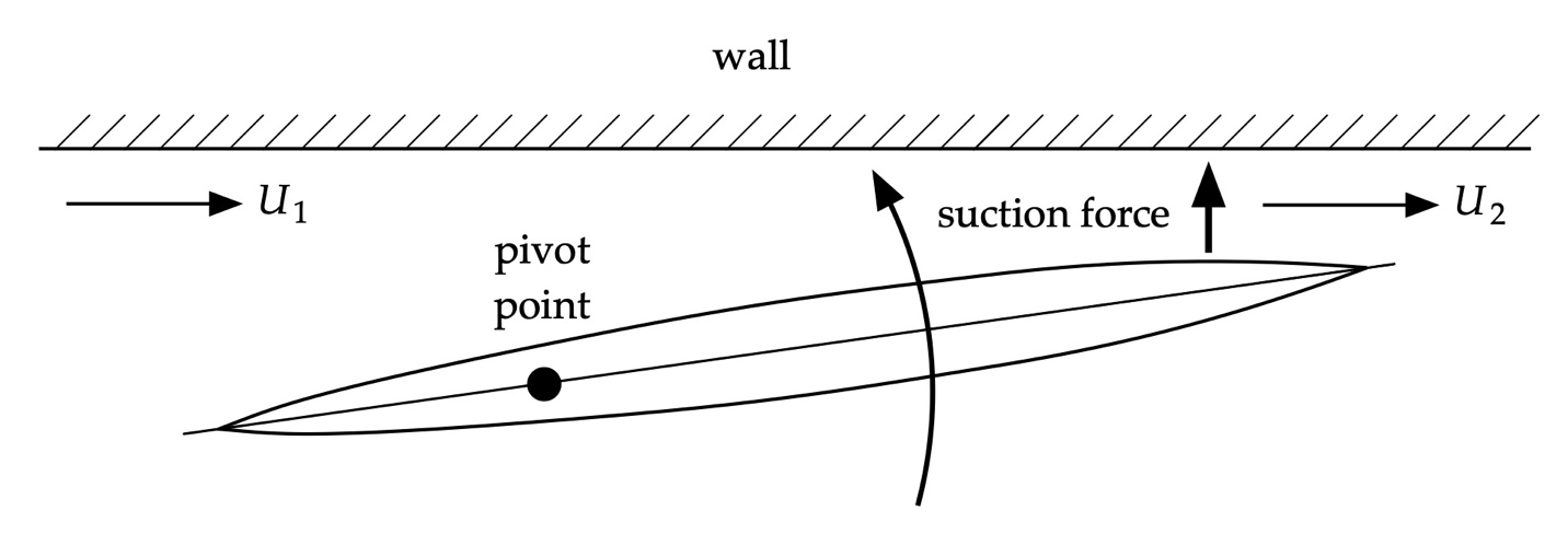
Figure 30: Hull and bank with initial yaw.
Hulls Moving in Parallel
Consider two craft moving in parallel as depicted in Fig. 31. Both are moving ahead.
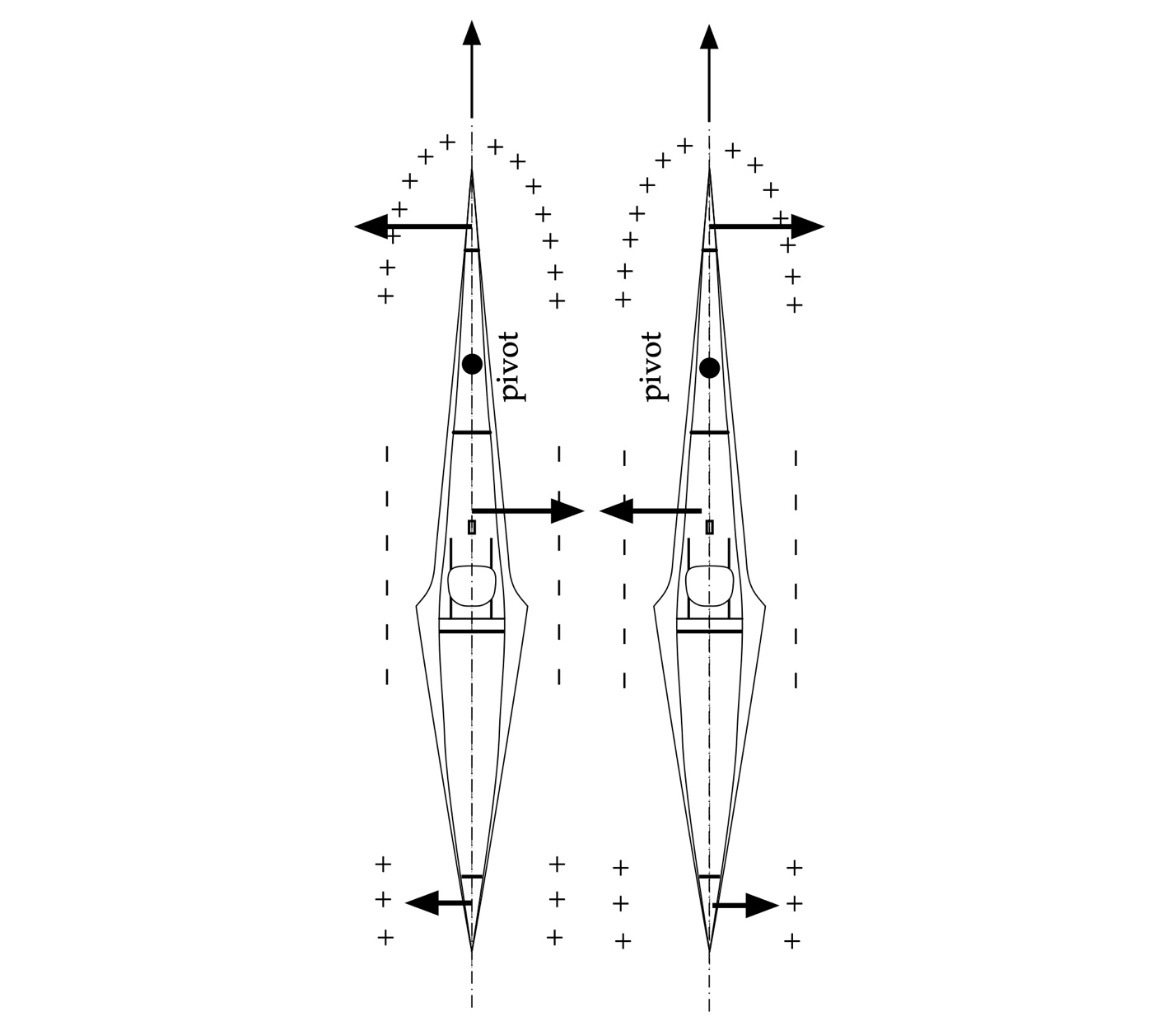
Figure 31: C1s moving in parallel.
As we saw in Fig. 9, the dynamic pressure alongside each hull is greatest near the bow because of water piling up there. As we move toward the stern there will be a low dynamic pressure region. Their speed ahead compared to hull speed may lead to additional regions of high and low dynamic pressure. Then, depending inversely on the spacing between hulls and to the square of their speed, the Bernoulli effect will create a suction force that pulls both hulls together. As the hulls pull alongside this force will act behind their respective pivot points. Any unbalanced forces will cause each craft to yaw away from the other, pulling their bows or sterns together depending on the nature of the unbalanced forces. This may require a downward lean on the adjacent sides, or corrective strokes to counter the suction force and prevent a strike. Striking each other is, of course, bad form.
Summary
In this installment of the Science of Paddling series we’ve tapped into reserves of TSOP knowledge to develop a compendium of handling scenarios. After reviewing the genesis of the various forces acting on our hulls, we used simple force and moment diagrams to consider what and why. This provides context for our paddling so we can keep our hulls well behaved in territories both familiar and unfamiliar. Or at least understand why we’ve lost control and are heading for a bridge piling.
The effects and scenarios outlined here are most significant when moving at higher speeds, smaller clearances, significant lean, and/or with hulls that are fuller below the waterline. Think of them as rules of thumb that will be more or less prominent – or urgent – depending upon your choice of hull and where you’re paddling.
© 2023, Shawn Burke, all rights reserved. For more information see the Terms of Use.
-
The translations of the laws of motion used here are from Bernard Cohen and Anne Whitman, The Principia: Mathematical Principles of Natural Philosophy, University of California Press, Oakland, California (1999) ↑