by Shawn Burke, Ph.D.
Introduction
We learned about surface waves in Part 35: Waves, Linear and Nonlinear. We saw that deep-water waves are dispersive – longer-wavelength waves travel faster than shorter-wavelength waves there. This causes wave shapes to gather, travel for a time, then decohere. Shallow-water waves are not dispersive and behave more like sound waves as they propagate. We can represent waves as a combination of sinusoids,[1] and these components maintain their phase relationship as they travel. This is a technical way of saying every wavelength travels together; the shorter-wavelength components have “caught up” to the longer wavelengths. And finally, larger-amplitude waves called solitons arise in shallow water of (at least relatively) uniform depth. These have a unique hyperbolic secant squared shape and an amplitude-dependent propagation speed. This amplitude dependence shows that solitons are a non-linear wave phenomenon, where the wave amplitude can be large compared to the depth. All the other wave phenomena we reviewed rely on the so-called “small wave” assumption. That’s Part 35 in a nutshell.
We’re now ready to look at the internals of water waves to understand wave breaking and why it’s possible to surf waves. Yes, we know folks surf watercraft like outriggers, and they’ve done it long before Isaac Newton did his thing. But since this is The Science of Paddling, we want to know why. We’ll then move to another of our favorite waves: the wave train behind a paddled hull. We’ll investigate the mechanism underlying successful wake riding using a different approach. A simplified model of wakes is used to deduce optimum and non-optimal stern wake riding positions.
We begin with wave orbits.
More About Waves
Surface waves, which arise from wind and fetch, can travel great distances and exert tremendous force upon ships and fixed structures like offshore oil rigs. But it is wave energy that is transmitted, not water. If, instead, water were bulk transported with surface waves, our oceans and lakes would have drained onto land long ago.
Still, there is some horizontal motion involved in surface water waves. Looking on and beneath the surface, we find water “particles” that move in circular orbits. This is because water waves contain components of both horizontal and vertical motion, and water molecules are connected by intermolecular forces. As shown in Fig. 1, the orbit’s diameter on the surface equals the wave height. These orbits progressively decrease in diameter as you dive beneath the surface. There is no more circular motion at a depth equal to half the surface wave’s wavelength. These circular orbits flatten in shallower water because of friction at the ocean or lake bottom.
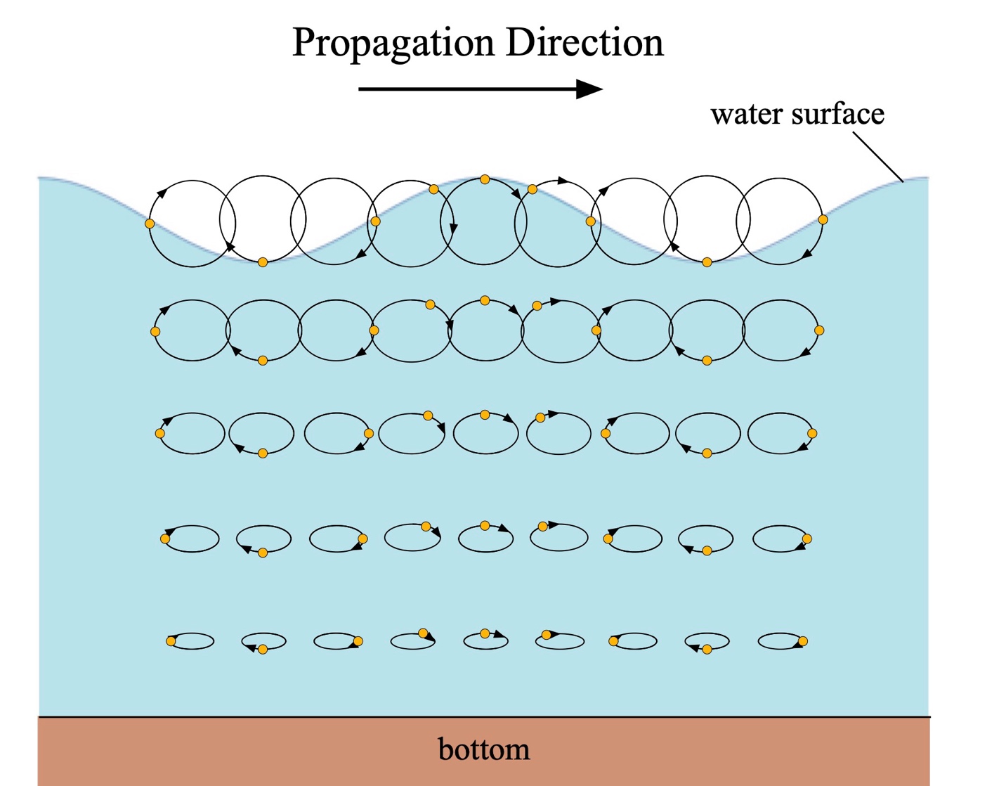
Figure 1: Surface waves and orbits (stretched vertical scale).
Let’s adopt an Earth-centric reference frame. As a wave passes, water particles ascend the wave’s front face, ride up and over the crest, and descend the wave’s back side. There is little horizontal movement, as shown in Fig. 2’s animation. If this weren’t the case, seabirds afloat on the ocean would be forcefully washed ashore with each wave.
Figure 2: Deep water wave orbits. (animation by Kraaiennest – CC BY-SA 4.0)
Deep water offers surfing opportunities when wave components cohere. When they decohere, the wave shape becomes indistinct, constantly morphing as different wavelength components pass each other at different speeds. Then as we’ve seen in Part 4: Shallow Water, shallow water waves are not dispersive. Their shapes begin to cohere, offering surfing opportunities before breaking over reefs and shallower water. This is shown conceptually in Fig. 3. Waves grow in amplitude as the water depth decreases because the total incoming energy must go somewhere. Remember, total system energy must be conserved. As we saw in Part 4, increasing wave height reflects increasing potential energy developed by raising water upwards in a gravity field. Here, the water goes up, and the wave height grows. The break then “falls” toward shore due to the direction of the water particle orbits as the back side “climbs” over the front. And because of gravity, the wash returns to the ocean or lake.
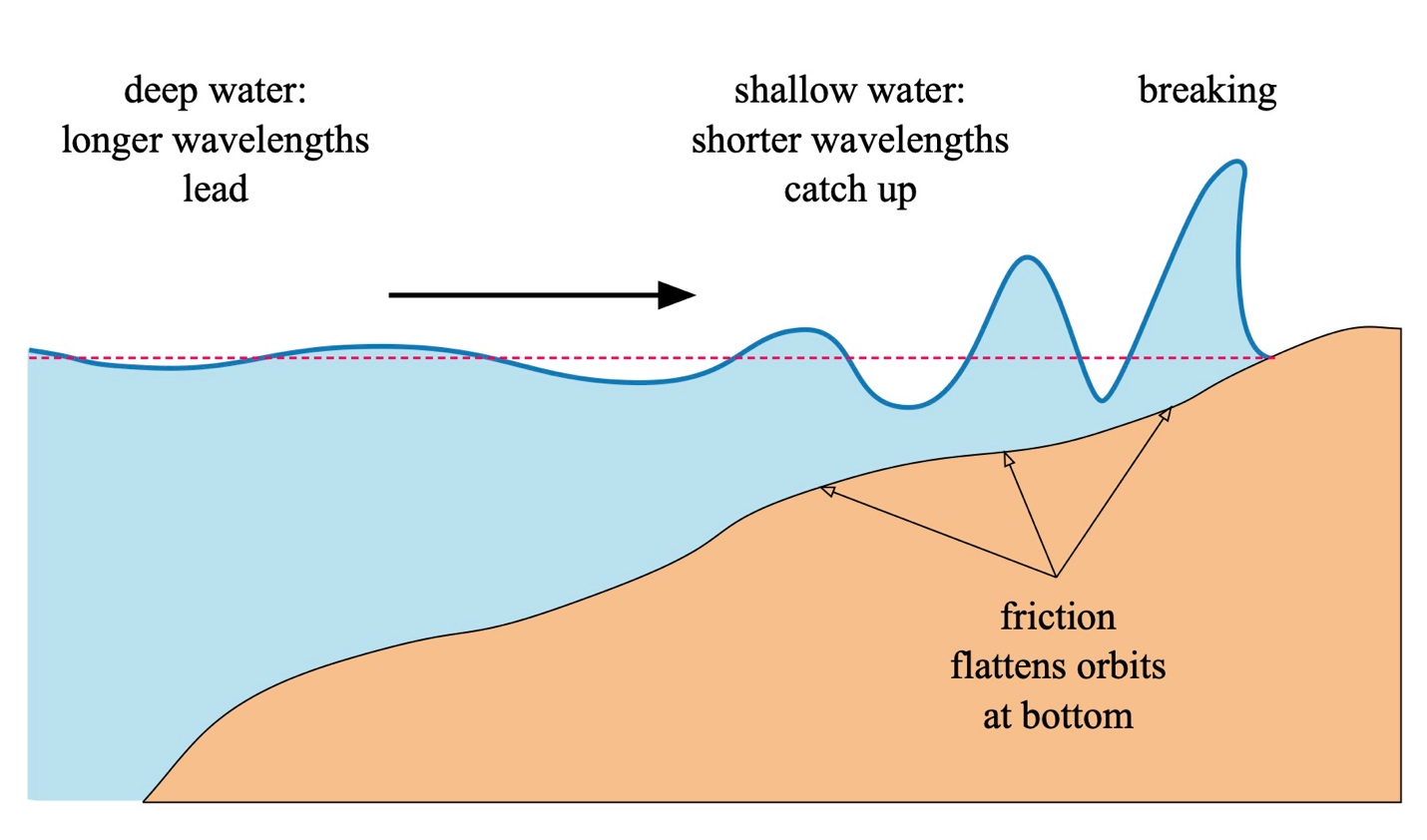
Figure 3: Breaking waves (not to scale).
Let’s Paddle
So now that we know more about why waves form and how they move, what can we do with that information? Certainly not teach people how to surf. Folks have known how to do that for a long time. But what’s going on when we surf an ocean wave? Fortunately, we have Newton’s 1st and 3rd Laws of Motion to help us.
The 1st Law states:[2]
Every body perseveres in its state of being at rest or of moving uniformly straight forward, except insofar as it is compelled to change its state by forces impressed.
The 3rd Law states, in short:
To any action there is always an opposite and equal reaction.
Consider the surfski paddler depicted in Fig. 4. We’ll change reference frames and adopt a perspective centered on the paddler. We’ll assume the paddler is surfing a wave having speed V in the horizontal direction. We’ll assume that the wave maintains its shape, at least for as long as we analyze it. The wave’s front face makes an angle q with respect to the horizontal. Since the paddler is surfing, they exert enough propulsive force Fp to stay in a fixed position on the wave. A buoyancy force Fb keeps the ‘ski and paddler afloat. The combined weight of the paddler and craft equals the product of their combined mass m and the gravitational constant g. Note that the weight, which is a force, is always directed downwards toward the center of the Earth; that’s how gravity works. Finally, as we noted from our review of Fig. 2, from the paddler’s point of view, water is continually flowing towards them. If the water’s surface speed relative to the hull equals some value U along the wave face, there must be a drag force Fd equal to the hull’s drag coefficient CD times the square of U.[3]
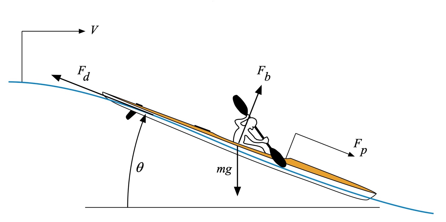
Figure 4: Wave surfing (not to scale).
In the paddler’s frame of reference, the hull is stationary unless the paddler falls off the wave by exerting too much or too little propulsive force. Consequently, Newton’s 1st Law holds. Without another applied force like cutting across the wave, or a wave that decoheres, you continue to surf.
Newton’s 3rd Law lets us understand the careful balance underlying the 1st Law here. This is most easily illustrated by considering just the forces at play, as depicted in Fig. 5.
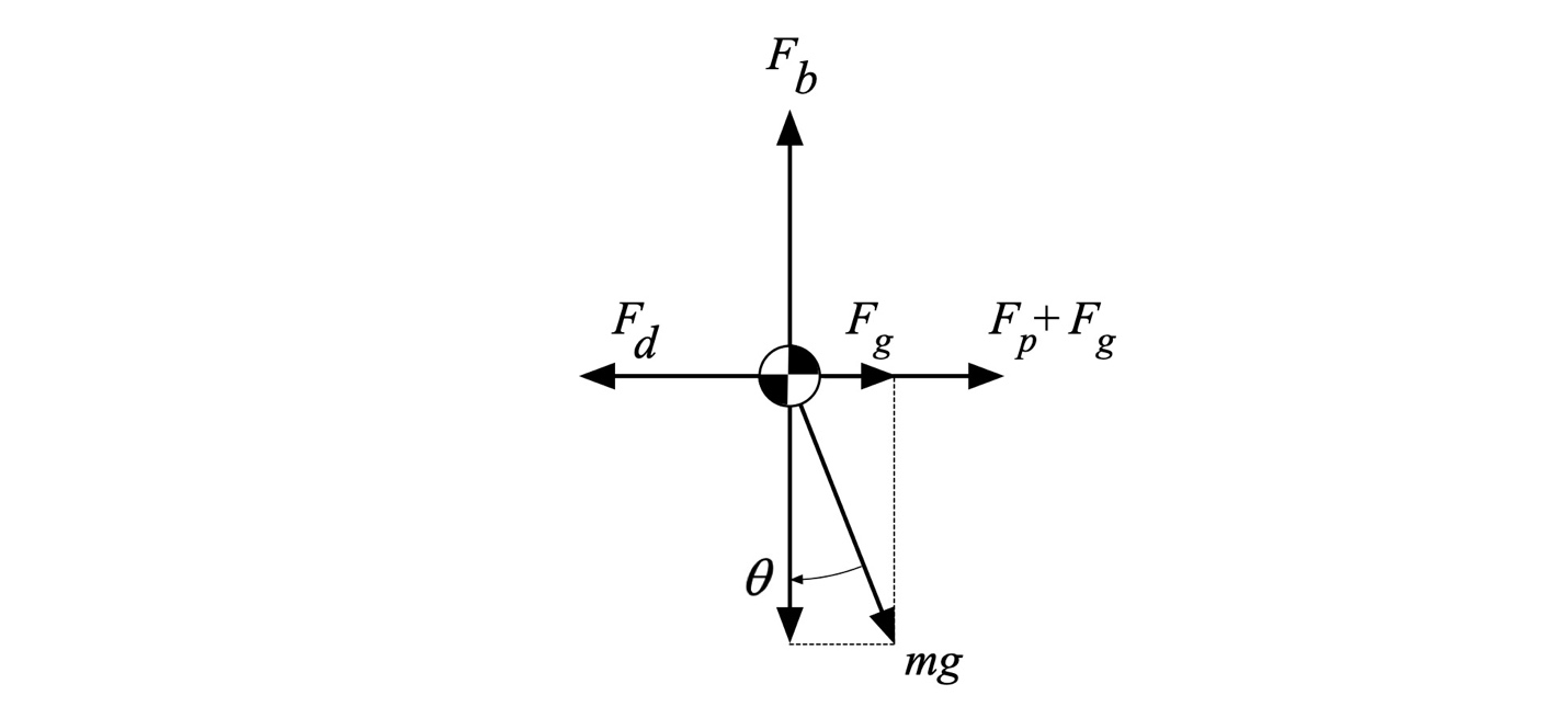
Figure 5: Force balance.
We’ve rotated the coordinate system to make things more straightforward. The horizontal axis in this figure aligns with the wave face, and “down” is to the right. First, in the vertical direction, the buoyancy force[4] Fb must have equal magnitude and opposite direction to the cosine of the weight. The cosine equals 1 when the ‘ski is “surfing” flat water, and the buoyance force exactly equals the combined weight – check! The cosine equals zero (0) when the wave face is vertical. At that angle, the buoyance force becomes irrelevant because you’re likely headed for a long swim as you (literally) fall off the wave. In between, the cosine reflects a weighting[5] of the component of the weight, which as a force is a vector quantity, in the direction vertical to the wave face.
The buoyancy force and the corresponding component of the weight vector must be equal and of the opposite sign so that their sum equals zero. Why? Because of Newton’s 1st Law. If the buoyance force was less, either the hull has sprung a leak or the hull is being sucked below the surface. If the buoyance force were greater, the hull would rise from the water and float away. Unbalanced forces accelerate an object in the direction of the imbalance. A balance of these two opposing forces reflects how the ‘ski stays on the wave’s face.
Similarly, the sine of the angle times the weight equals the component of the weight directed down the wave’s face. When the angle equals zero – flat water – there is no force due to the weight exerted along the wave’s surface. When the wave face is vertical, and the angle equals 90 degrees, the sine equals 1, and the “propulsive gravity force” Fg equals the weight mg. In between, the sine reflects a weighting of the component of the weight in the direction along the wave face.
The total propulsive force is the sum of the paddler’s propulsive force Fp and the component of weight in that same direction, Fg. In the paddler’s reference frame, the surfski is stationary with respect to the wave. From Newton’s 1st Law, there can be no unbalanced forces. Consequently, the drag force Fd precisely equals the total propulsive force Fg + Fp. As the angle steepens, the propulsive force needed to balance the drag force becomes less and less. This is because the component of weight contributing to the total propulsive force is increasing. This delicate balance of forces is just Newton’s 3rd Law in action.
Wake Riding
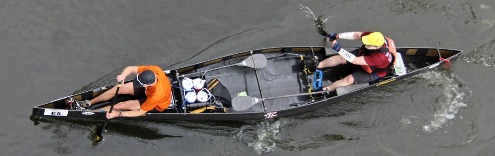
Now what about the waves we see behind paddled craft? Wake riding is a skill most flatwater marathon and ultramarathon paddlers want to have in their toolbox. But there’s nothing new about wake riding. Waterfowl do it all the time, as shown in Fig. 6.

Figure 6: Some ducklings wake riding (photo courtesy Tina Philbrick Richard).
As ducks and geese mature, they learn to ride in line behind mama, unlike the higgledy-piggledy clump shown in the figure. Experienced flatwater paddlers know this saves energy in long races. Hey, we’re not inventing the wheel here! But the question is, why does it work?
We’ll take a different tack for analyzing wake riding and consider the hydrodynamics in terms of the pressure field induced in the water by the wake. We’ll skip the math because it’s frightfully messy and focus instead on the implications.
Now in quiet water, with no wake to ride, the hull is subject to a hydrostatic pressure force without a horizontal component. This is shown in Fig. 7. This pressure distribution is symmetric about midships. Consequently, it only supports the hull, not contributing to its forward motion.
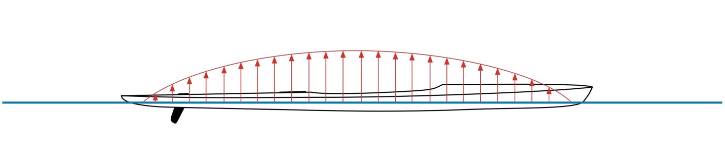
Figure 7: Pressure distribution on hull, flat water (not to scale).
Consider a hull perched on a wave, as shown in Fig. 8. We’ve used a Fourier series decomposition of the wave shape[6] and only retained the first term. This is a precise way of saying you can represent the wake’s profile using a combination of sinusoidal shapes of different wavelengths, and keeping only the first term is a pretty good approximation. The hull is sitting on a wave with its stern near a wave crest and its bow near a wave trough. Since the wave height reflects the pressure distribution exerted on the hull, an extra propulsive component in the direction of movement arises due to the sum of the pressure over the hull’s wetted area. This distribution is propulsive because pressure gradients push things in the gradient’s direction; it’s referred to as a positive pressure gradient. This mechanism is why garden hoses work, for example. There is a pressure difference (gradient) between the pressure inside the hose and the ambient pressure outside; hence water flows from the hose. For our hull, the gradient means less propulsive effort is required than paddling on calm water. Less propulsive effort for the same speed means we can think of wake riding effectively reducing the hull’s wave drag. We’ll enjoy this benefit as long as the relative position of the hull and wave remains unchanged. This requires that the hull’s forward speed equal the wave speed. A propulsive effort is still needed, but less than in the wake’s absence.
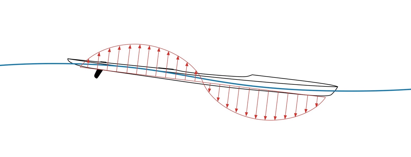
Figure 8: Pressure distribution on hull, wake riding (not to scale).
Consider a hull perched differently on a wave, as shown in Fig. 9. The hull sits on a wave with its stern near a wave trough and its bow near a wave crest. Since the wave height reflects the pressure distribution exerted on the hull, an extra net force opposite the direction of movement arises due to the sum of the pressure over the hull’s wetted area. This distribution acts opposite our direction of travel because negative pressure gradients pull things in the gradient’s direction. This is why vacuum hoses work, for example. There is a pressure difference (gradient) between the pressure inside the vacuum and the ambient pressure outside; hence stuff flows into the vacuum’s hose. For our hull, the gradient now means more propulsive effort is required than paddling on calm water. More propulsive effort for the same speed means that we can think of wake riding this way as effectively increasing the hull’s wave drag. We’ll experience this degradation in performance as long as the relative position of the hull and wave remains unchanged. This is why it takes added paddling effort to pass over a wake.
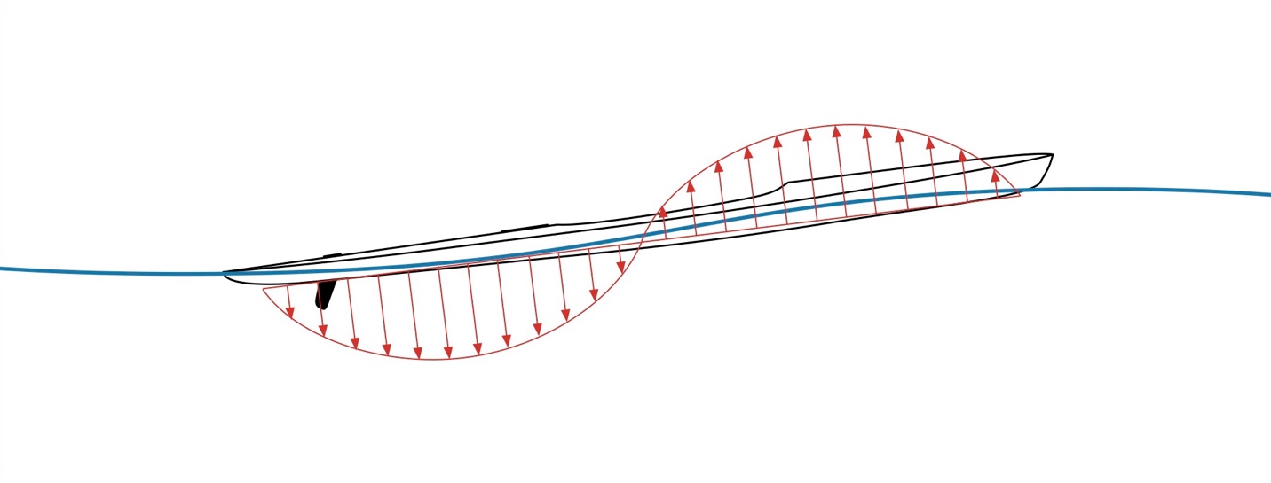
Figure 9: Pressure distribution on hull, wake climbing (not to scale).
The preceding analysis begs the question of whether there is an optimal location on a wave train for wake riding. We can build a model subject to a few assumptions to answer this. First, we assume the lead hull is running at its hull speed or a little above, and the trailing hull has the same length. Using our wave profile approximation and assuming the trailing hull is symmetric fore-and-aft, we find that there is a sweet spot. This is illustrated in Fig. 10, which plots our approximate wake profile from the leading hull on the right, with the wave train extending from right to left. Also on this plot is a scaled version of the effective wave drag reduction as a function of the hull’s midship position.
As you can see from the plot, the effective wave drag reduction effect is optimized when the hull’s midship is atop the quarter-wave point in front of each wave in the wave train. These quarter-wave points correspond to the zero crossings of the blue wave profile points. Forward of these points, the benefit decreases until there is no effect. Then the effect becomes detrimental until the next wave is crested, and so on, until you bang the stern of the lead boat. At this point, the leading paddler, especially in a tandem hull, dumps paddles full of water into your craft.
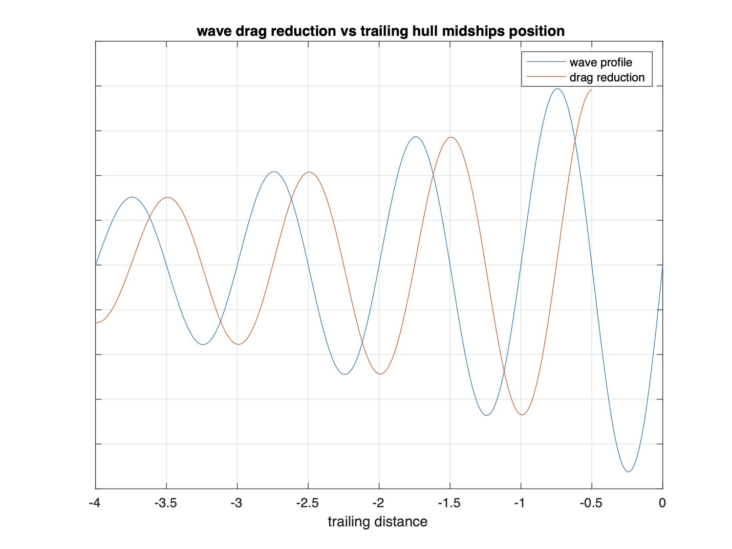
Figure 10: Wake wave pattern and wave drag reduction vs. position (not to scale).
So why does the benefit diminish the further back you are on the wave train? This is because the corresponding wave heights decrease, and the effect is proportional to the wave height. Wave heights diminish the further you are behind the lead hull because of the conservation of energy and mass, as suggested in Fig. 11.
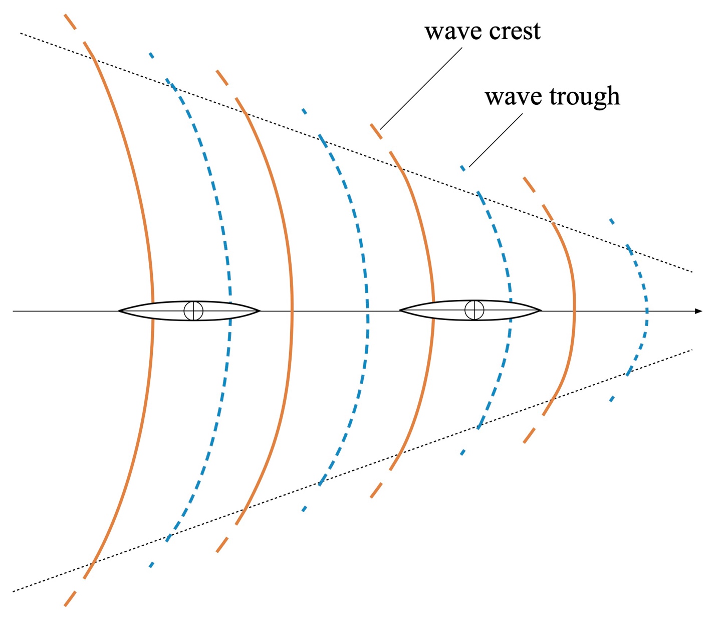
Figure 11: Wake wave pattern, plan view, and riding locations.
Fig. 11 shows the Kelvin-Froude wave pattern we see behind paddled craft. This pattern spreads out in a fan behind the lead hull. Each trailing wave must distribute the wave-producing energy the lead hull provides across its width. Since each wave crest’s total potential energy in 3D is the same, and the mass of water is conserved (we aren’t adding any sources or sinks of water), when waves spread horizontally, they must be of lower height than those toward the pattern’s front. The height also diminishes as we move away from the lead hull’s keel line. That’s why we get less of a “bump” from riding the third wave than the first wave and progressively less as you move to the side. Then again, it’s easier to climb those shorter waves, too. If you want to “slide” onto a big wave, starting from the side and working toward the middle is often easier.’ I’ve found this approach helpful for getting on a tandem’s wake when paddling C-1.
Another effect of this wave pattern divergence and curvature is that it’s easiest to stay in line behind the lead hull. There are stabilizing forces right behind certain hulls that serve to keep you lined up. Otherwise, you’ll encounter cross forces that try to turn you – alterations in the pressure gradient as you change position relative to the wave pattern. The trailing hull “wants” to ride perpendicular to the wave crests. If you’ve ever shot off at an angle when passing over a lead hull’s first stern wave, you know what I mean.
Wave riding is an art and a skill to be developed. In practice, the optimum ride will place the riding hull’s midship close to the quarter-wave points described above. Still, it will likely need a little tweaking.
Summary and Conclusions
Folks have been wave and wake riding for quite some time. Marine wildlife and waterfowl have been doing it for even longer! So, in this installment in the Science of Paddling series, we dug into why it works.
We first learned that water waves are primarily a means for energy propagation, not bulk fluid transport. Still, the water column has a small amount of horizontal motion. This motion comprises water particle orbits. These orbits trace trajectories synced to the wave as it travels past. They diminish in amplitude the deeper you are below the surface and vanish at a depth equal to half the wave’s wavelength. The orbits encounter bottom friction in shallow water, distorting and slowing the deeper orbits. Waves break toward the shore rather than away from it due to these orbits’ orientation (or “handedness”).
We next studied why riding a wave takes less paddling effort than paddling on flat water. For a wave having a fixed profile, we considered one mode of surfing that maintains a fixed position with respect to a wave’s shape. Just enough propulsive force is exerted to stay there. The benefit accrues because of the component of the paddler and hull’s combined weight, which provides an additional propulsive force due to the wave face’s incline. This configuration reflects Newton’s 1st and 3rd Laws. In the paddler’s reference frame, the hull isn’t moving, and all forces acting on the hull are balanced by equal and opposite reaction forces.
We then considered wake riding the wave train behind a paddled hull. Without diving into a tangle of partial differential equations, we showed the mechanism underlying successful wake riding effectively changes in the trailing hull’s wave drag from the gradient of hydrodynamic pressure on the hull. If the trailing hull sits on the wake’s quarter-wave points, this change is most beneficial; if it sits on the three-quarter wave points it’s most detrimental. The effect diminishes the further you trail the lead hull and drops as you move to the side of the lead hull’s keel line. This is because the effective wave drag change depends on the wave height. Waves grow smaller behind and to the side because of energy conservation over the Kelvin-Froude wave pattern’s fan.
I hope to look at side wake riding in some future installment and address wake mismatching of hulls having different lengths, as well as the suction force from the Bernoulli effect as a function of inter-hull spacing – one more chance to revisit the important qualities of wave superposition.
Further Reading
G.B. Whitham, Linear and Nonlinear Waves, Wiley-Interscience, New York (1974).
H.F. Weinberger, A First Course in Partial Differential Equations, Dover Books, New York (1965).
F.G. Tricomi, Integral Equations, Dover Publications, New York (1985).
H.S. Carslaw, An Introduction to the Theory of Fourier Series and Integrals, Dover Publications, New York (1950).
Georgi Tolstov, Fourier Series, Dover Publications, New York (1976).
V1.0
© 2023, Shawn Burke, all rights reserved. Please see the Terms of Use for more information.
- Sinusoids form a “complete basis” for wave shapes. This means any non-discontinuous wave profile is a superposition of sine functions of different wavelengths, with the difference between the shape and the superposition vanishing due to Parseval’s Theorem. A good analogy is Western music, which comprises notes corresponding to twelve semi-tones in each octave. This “tempered tuning” yields a set of notes – a basis – that can construct “all” songs (e.g., is complete for “all” pieces and not missing any notes). By contrast, Indian music uses seven major tones, five flats/sharps, and twenty-two shruti per octave as the basis to construct Indian classical music. ↑
- These the 1st and 3rd Law translations are from The Principia: The Authoritative Translation by Cohen, Whitman, and Budenz, the University of California Press (2016). ↑
- See Part 14: Kind of a Drag for the drag coefficient’s role and Part 26: Waking Up for a derivation of the drag equation. ↑
- See Part 19: Roll Your Boat for more about buoyancy and the buoyance force. ↑
- No pun intended. ↑
- For more on this, see, for example, F.G. Tricomi, Integral Equations, Dover Publications, New York (1985) – such a great book!, H.S. Carslaw, An Introduction to the Theory of Fourier Series and Integrals, Dover Publications, New York (1950), and Georgi Tolstov, Fourier Series, Dover Publications, New York (1976). ↑