by Shawn Burke, Ph.D.
I curiously watched a tandem canoe paddler as I tried to wipe the sleep from my eyes on Memorial Day at Lakefront Park. He was alternately spraying a clear liquid on the bottom of his high-end racing hull, and then madly buffing it. I thought he might be practicing some new way of warming up before the annual General Clinton 70-miler. I learned instead that the he hoped to make his boat faster by coating it with this “liquid speed.”
I asked about all the scratches on the hull, and if perhaps they might slow him down a bit. He admitted that there wasn’t much he could do about those on race morning. But he fervently believed that the magic goo he was applying to the bottom of the hull would more than compensate for the scratches.
Back in the day I spent a couple of years of graduate school doing research at a water tunnel[1], exploring novel techniques for drag reduction on seagoing vessels. And I know that in certain cases continuously injecting liquid polymers or air bubbles into the flow adjacent to a hull can reduce drag – more on that later. But these exotic techniques don’t work in the way that tandem paddler hoped his hull polish would work. Period. In light of some basic physics – in this case, hydrodynamics, which is the study of fluid flow – the more pertinent question was how much of a penalty he and his partner were going to pay for all of those scratches in their hull.
The biggest misconception people have about waxes, polishes, and other sources of “liquid speed” is that they somehow allow their hulls to slip through the water faster. Or that by some magic water won’t “stick” to the hulls as easily if they are so treated. Nothing could be further from the truth. There are other possible benefits from polishes, and we’ll address those later. But in terms of making a boat more “slippery” in the water, well, not so much. To understand why, let’s look at what happens as water flows over our canoes, kayaks, dragon boats, and SUPs.
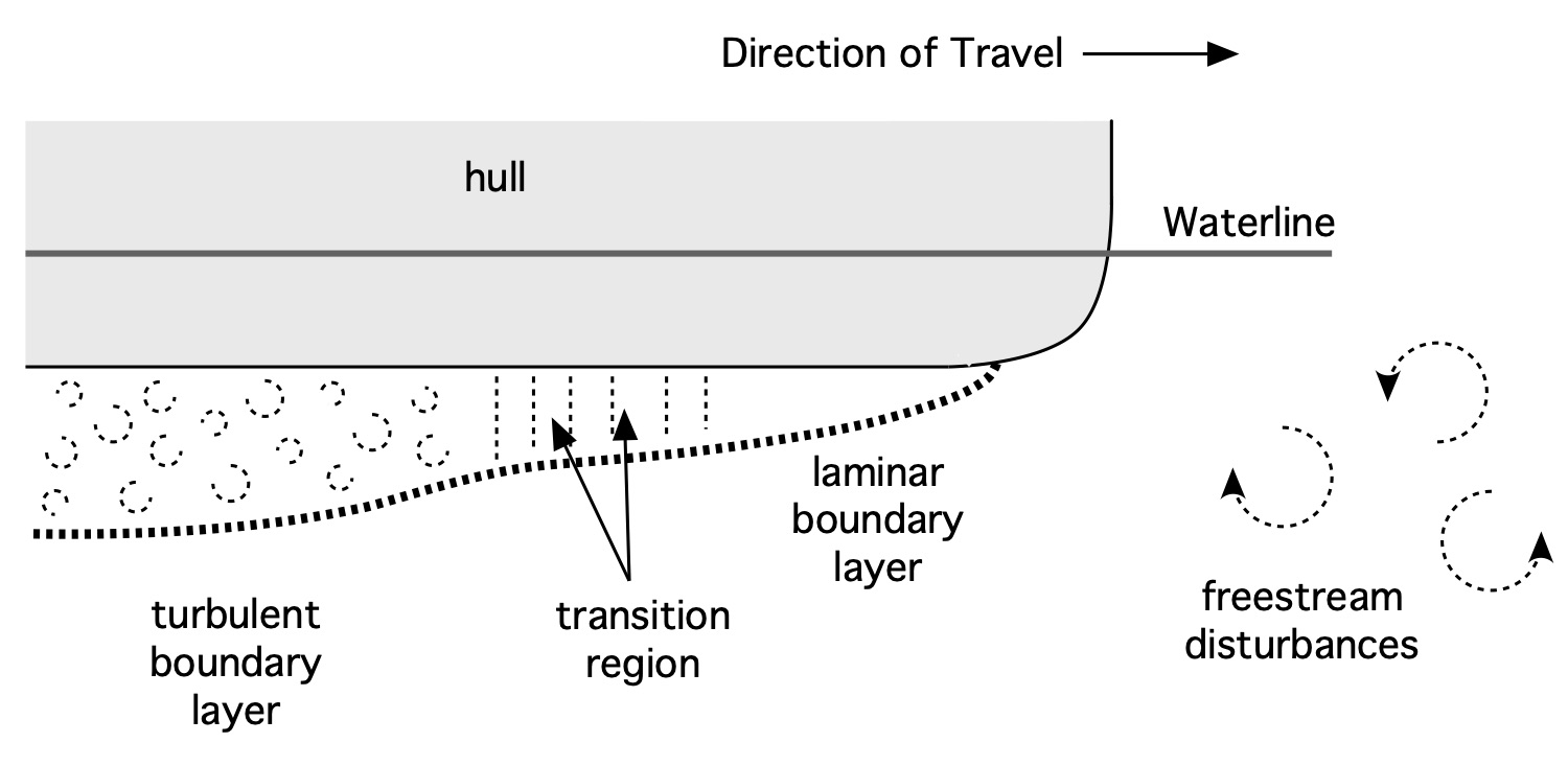
Figure 1: Water flow beneath a hull (not to scale).
Consider the flow of water along a hull as depicted in Fig. 1. In this Figure the boat is moving from left-to-right in quiet water. We’ll assume that the boat is up to speed and traveling at a steady pace. We’ll also adopt a paddler’s frame of reference, where we think of the water as flowing past the hull rather than the hull past the water. This change of reference, called a Galilean transformation, lets us move between any frames of reference that differ by a constant relative velocity. The physics are easier to understand this way.
As water approaches the hull its constituent molecules, loosely bonded to each other by cohesive molecular forces[2], are free to move anywhere they want as a liquid. When they first encounter the boat something interesting happens: the water molecules that contact the hull actually adhere to it. Right at the hull surface the water molecules and the hull move together. Since we’ve adopted a hull-centric frame of reference this means the water right at the hull’s surface has zero velocity with respect to the boat and paddler. This is called the no slip condition in fluid mechanics. The no slip condition holds whether the hull is made of Kevlar, carbon fiber, wood, fiberglass, aluminum, plastic, or anything else for that matter. And the no slip condition holds whether the hull has been coated with “liquid speed,” a UV protectant, carnauba wax, or slime from your last paddling session. In all of these cases the relative speed between the hull, and the water immediately in contact with the hull, is zero[3]. Period.
Now we know that water flows past the hull as we paddle; if all of it stuck we wouldn’t be able to move. What happens to the water that isn’t in contact with the hull, but is instead “close” to it? This is where the concept of a boundary layer comes into play. Boundary layers are the source of friction drag that is constantly trying to slow you down.
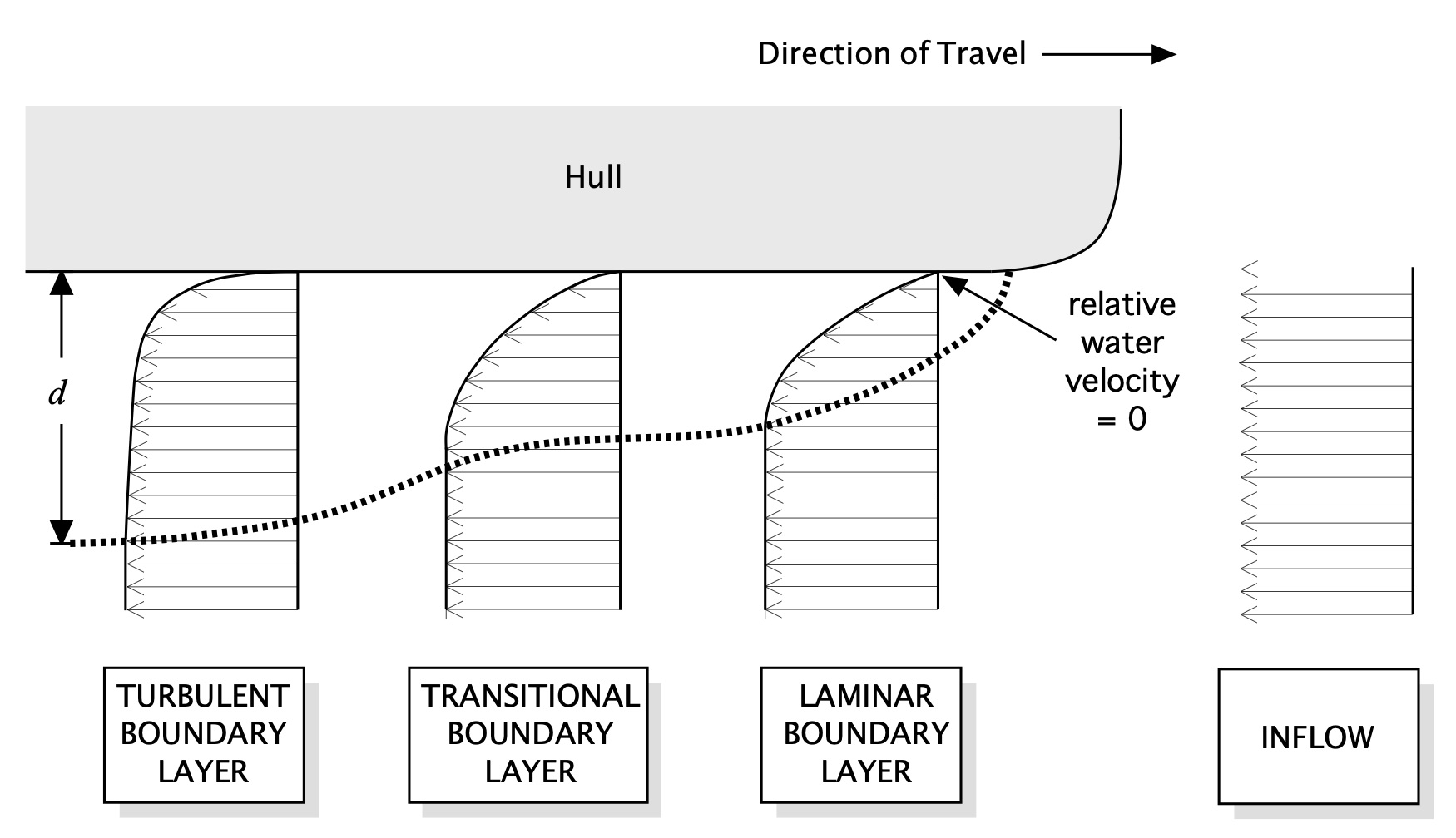
Figure 2: Boundary Layers (not to scale).
The no slip condition requires the water’s relative speed at the hull to be zero. From our Galilean transformation the so-called free stream speed of water far away from the hull will equal the hull speed. Consequently, there is a variation or gradient in the water’s relative velocity as we move away from the hull’s surface until the water’s velocity equals the free stream speed. The region where this gradient exists is called a boundary layer.
Boundary layer shapes are conceptually illustrated in Fig. 2 for laminar, transitional, and turbulent flow. The thin horizontal arrows denote the average flow speeds at various distance from the hull; longer means faster. The dotted line denotes the thickness of the boundary layer where (for example) the flow speed equals 99% of the free stream speed. The boundary layer grows thicker as you go from the front of the hull to the back for reasons we’ll detail below. And as suggested by the different boundary layer profiles in the figure, the internal character of the boundary layer changes as well.
A laminar boundary layer develops near the front of the boat. The water impinging on the hull travels uniformly in this case. If you injected colored dyes in the water just upstream of the bow you’d see that the dyes moves along the hull there in nice, parallel lines, hence the term laminar – like laminations. The laminar boundary layer depicted in Fig. 2 has a fairly gradual gradient in the water’s speed as you move away from the hull. The slope of this gradient is indicative of the frictional forces on the hull. The more gradual gradient in the laminar case reflects lower wall shear stresses, which means less energy loss and thus lower frictional drag. In fact, if the flow over the entire hull was laminar the frictional drag would be greatly reduced, and you’d go a bit faster.
Laminar boundary layers are sensitive beasts. Think of a laminar boundary layer as like a little channel of water adjoining the hull. Inside this channel there is not only smooth-flowing water, but also tiny pressure oscillations that aren’t all that different from sound waves. These pressure waves – called Tolmein-Schlicting or “TS” waves – travel inside this laminar boundary layer channel in the direction of flow, from the front of the hull towards the back, much like sound travels down a long hallway. TS waves are initiated by small disturbances in the upstream flow, such as those encountered when paddling in swirly or turbulent rivers, or when closely following another boat.
The TS waves differ from ordinary sound waves in one very important aspect: they grow in amplitude as they travel. After they travel a certain distance they will have grown in amplitude enough to begin influencing and then disrupting the laminar boundary layer’s orderly structure. The nice parallel streamlines of the laminar flow start to wiggle and distort under the influence of these growing pressure waves and become disorganized. At this point the boundary layer is starting to transition from laminar to turbulent, hence the transition region shown in Fig. 1.
The location along the hull at which transition occurs is determined by the speed of the hull, and the viscosity of water. If we represent the hull speed over the water as U, and the kinematic viscosity of water as 

The expression on the left-hand side of this equation is called the Reynolds Number, and is often written as “Re”; more on this in a bit. When the Reynolds number equals approximately one million the flow over the hull becomes turbulent. For a solo racing canoe traveling at 6.3 mph (2.8 m/s) in 68F (20C) water, transition occurs a mere 14 inches (35.4 cm) from the front of the boat. The length of the transition region will be even shorter. For this hull, which is 18’6” (5.64m) long, we see that the flow over the majority of the hull is turbulent. And if the upstream disturbances in the flow are large, perhaps due to whitewater eddies or the wake of a boat you are following, then transition will occur even closer to the bow.
Once the flow is turbulent there are no longer any nice, orderly streamlines inside the boundary layer. Instead, the flow there becomes chaotic and highly three-dimensional. This is illustrated by the flow visualization in Fig. 3. In this plan view we’re looking at a portion of the bottom of the hull from below, with water flowing from right to left. A dye has been injected into the water upstream at a number of points spaced across the hull’s width. Notice how the streamlines changes from nice parallel lines to a chaotic structure as the flows transitions to turbulence. You can also see oscillations in the streamlines in the transition region just upstream of the large turbulent burst. The flow continues its chaotic nature downstream of this area as the boundary layer becomes fully turbulent. The slope of the averaged velocity gradient inside the now turbulent boundary layer becomes more pronounced, more “full,” than in the laminar case, as depicted in Fig. 2. This reflects the frictional forces due to shear stresses on the hull’s surface, which are greater than for laminar flow. The boundary layer itself becomes thicker, as you are putting more of your precious paddling energy into generating turbulence.
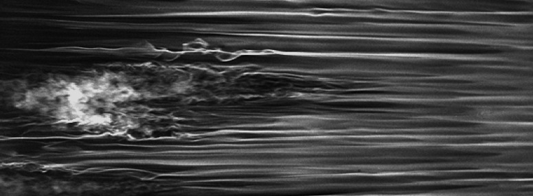
Figure 3: Flow visualization: Plan view of a boundary layer becoming turbulent.
While there are ways to extend the region over which the flow over a hull is laminar, they tend to involve fairly impractical measures like generating out-of-phase sound waves ahead of the hull (as demonstrated by my grad school office mate Chuck Gedney in his Ph.D. thesis), or selectively heating the hull surface (as demonstrated by Dan Nosenchuck in his Ph.D. thesis at Cal Tech), to interfere with the TS waves’ growth. Even then, the transition location is delayed – i.e., moved toward the stern – by about ~50% under ideal laboratory conditions. When it comes to turbulence and friction drag, you can’t win, you can’t break even, and you can’t get out of the game.
Now the no-slip condition, boundary layer transition, and turbulence are going to be there whether you coat your hull in magic goo or not. But are there any things you can you do to make your boat go a little faster? Aside from buying a faster hull shape – and more training! – the first thing to consider is the condition of your hull. Many of us who paddle on shallow rivers have had one or more close encounters with logs and rocks. The resulting scratches are a concern. But should they be? Are some scratches worse than others?
It is well known that most minor imperfections in a hull’s smoothness will slightly increase viscous drag, on the order of a couple percent. At the other extreme, a group of students at the University of Michigan took an aluminum canoe, bludgeoned it with sledgehammers all along its length, and measured the resulting increase in drag force in a towing tank. The amply distorted hull exhibited about a 6% increase in total drag; so how bad can your hull be?
Keep in mind viscous drag is only one component of the total drag force exerted on a hull as you paddle it, as shown in Fig. 4. As you approach the so-called hull speed (see Part 4: Shallow Water) viscous drag will be overshadowed by wave drag effects, which are properties of the hull’s shape and the fact that you’re paddling along the interface between water and air. So addressing a 1% increase in viscous drag by polishing a hull will result in at most a comparable decrease in total drag, and will be most noticeable at lower speeds.
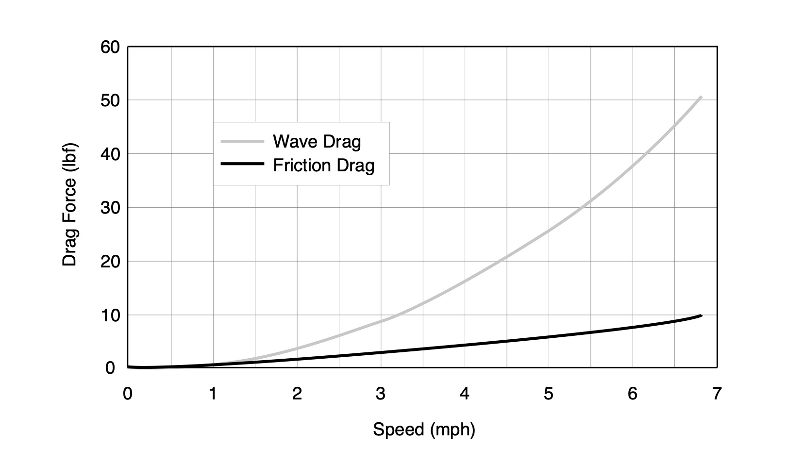
Figure 4: Example of drag forces vs. speed.
But how rough is rough? If a hull is “smooth enough,” will it slip through as if it were “perfectly” smooth? And, is there a rule of thumb regarding roughness for those of us who really obsess about our hulls? Well of course!
Even though the flow over nearly 95% of our hulls is turbulent, there is an exceedingly thin layer of the flow immediately adjacent to the hull’s surface that is laminar, no matter what. This laminar sublayer is far thinner than the boundary layer in which it resides. The laminar sublayer exists because there is a difference between molecular diffusion and the propagation of vorticity, the latter of which describes turbulence in the outer boundary layer – in other words, serious techno babble. The importance of the sublayer to our discussion is that it is the key to understanding how surface roughness impacts drag on our hulls.
Like the laminar portion of the boundary layer itself, the laminar sublayer is easily disturbed. Hull roughness can destabilize the sublayer, leading to increased turbulence through a process called bursting where microscopic jets of water launch away from the hull into the main boundary layer, further energizing the turbulence there and increasing drag. But suffice it to say that as long as the height of any surface roughness is small relative to the thickness of the laminar sublayer, then the hull will behave as if it is smooth; the sublayer will continue to be stable and laminar.
The laminar sublayer thickness, represented by 
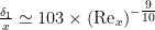
where Rex is the Reynolds number cited above, where the length scale is now the distance x from the bow. Fig. 5 is a plot of the sublayer thickness along the hull for an 18.5-foot hull running at 6.3 mph (2.8m/s) in 68F (20C) fresh water. Note that the sublayer thickness is inversely proportional to a power of hull speed U, which means the sublayer is thinner the faster you go. A thinner sublayer exacts a more demanding limit on hull smoothness: the faster you go, the smoother your hull needs to be to keep the sublayer stable.
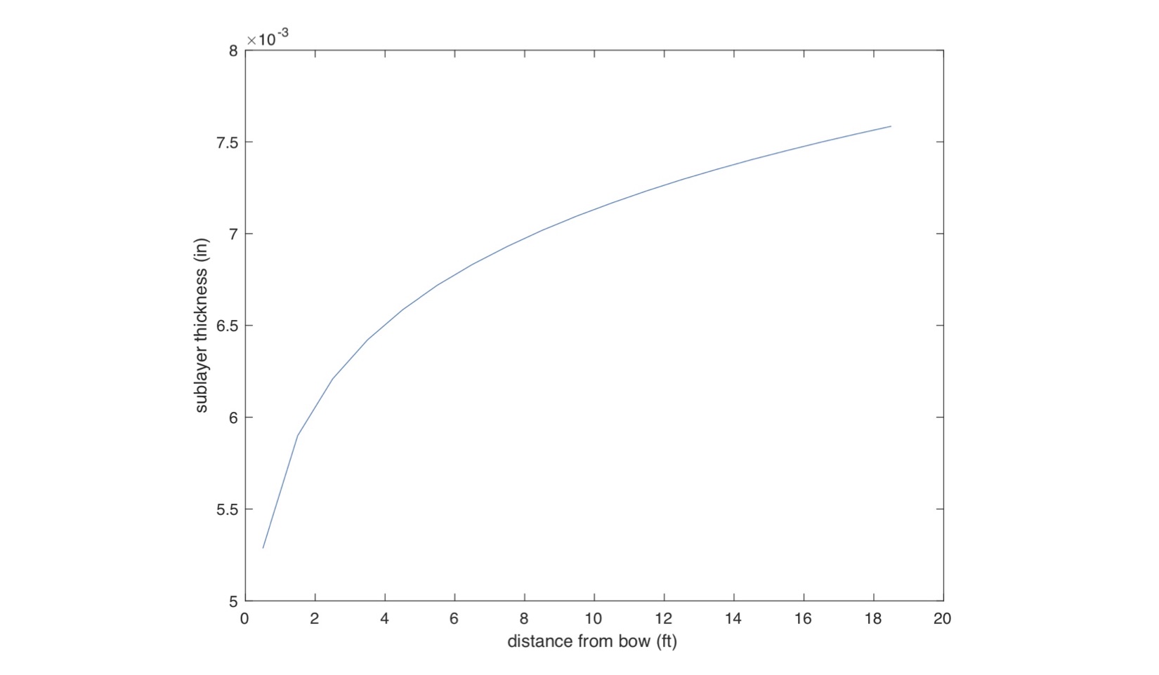
Figure 5: Sublayer Thickness (mils) vs. Distance Along the Hull (ft).
Fortunately for us paddlers we don’t move all that fast, at least compared to a car or a jet. As you’ll note from the plot, the sublayer thickness for our hull at 6.3 mph varies from about 5 thousandths of an inch near the bow to around 8 thousandths of an inch near the stern. So to ensure that your hull is hydrodynamically smooth, make sure it is no rougher than about 1 to 1.6 thousandths of an inch average roughness height, or about one fifth of the sublayer thickness. In more familiar terns, 1.4 thousandths of an inch is about the average grain size of 320 grit sandpaper. If your hull is as smooth as that, as far as the water is concerned it is perfectly smooth. Roughness greater than that will introduce more turbulence into the boundary layer, resulting in an increase in frictional drag.
So where should you focus your energy and resources to reduce friction drag, if anywhere? Certainly, a scratched and rough hull will foul more easily, and deep scratches should be repaired if for no other reason than to prevent moisture penetration into the underlying fibers of a Kevlar, fiberglass, or carbon fiber lay-up, or the wood of a stripper or wood-canvas layup. Those are reasons enough to keep a hull in good repair. And if you really want to do some polishing, and the polish fills or grinds down any superficial scratches, then there will be a small decrease in frictional drag. This will most important in the leading couple of feet of the hull, since small surface imperfections there can help destabilize a laminar boundary layer and lead to an even earlier transition to turbulence. So by all means polish the bow and the front meter or so of the hull, and keep the rest smoother than around 0.002”.
And as to employing “liquid speed,” the chief benefactor there may lie between your ears. If you feel that it makes you paddle faster, you probably will.
APPENDIX: Novel Drag Reduction Techniques
In the 1980s there were several studies that characterized exotic approaches to turbulent drag reduction, such as compliant skins, injecting long-chain polymers or air bubbles into the flow, and “scoring” surfaces along the direction of flow. In summary:
- The jury is still out on whether compliant (e.g., elastomeric) hull surfaces reduce drag. But it was an interesting technology to explore, and funded two years of graduate school for me.
- Injecting a cloud of tiny air bubbles into a boundary layer can have a huge effect in decreasing drag. You are in essence encasing the hull in a thin envelope of air, so now you mostly have to counteract the drag force arising from moving the hull through air, rather than through water – much less friction. Rumor has it that this technology has been incorporated into high-speed torpedoes. Incorporating an air injection system into racing hulls would entail a lot of equipment, weight, and space, so it’s not very practical for our needs. The displacement penalty from the added weight would more than offset any reduction in friction drag, as noted in The Science of Paddling, Part 1.
- Injecting long-chain polymers into a turbulent boundary layer can measurably reduce drag. It apparently works by dampening the growth of turbulence in the cross-stream direction. And by “long-chain polymers,” think of something like cooking oil. In order for this to work you have to controllably inject thin streams of it into the boundary layer the entire time you are under way. I doubt I’ll be seeing pit stops at the General Clinton with crews re-supplying water, food, and canola oil.
- 3M used to sell a type of polymer sheeting that had parallel, triangular grooves (“riblets”). The grooves were 6 thousandths of an inch tall, spaced 6 thousandths of an inch apart. The sheeting was adhered to a hull with the grooves aligned in the direction of flow. Under certain conditions, surfaces with this “ribbed” covering experienced a drop in viscous drag ranging from 2 to 8 percent. This material was tested on rowing shells. Unfortunately, while there seemed to be some initial effect in reducing drag, the next day the effect disappeared. This may likely be attributable to surface fouling between uses. Remember, a 6 thousandth of an inch feature is quite small, easily damaged, and easily filled with river slime. I have heard of more lasting results from the ‘80s applying the 3M sheeting to sprint kayaks, but have yet to find any published article or quantitative test data so support what I’ve heard.
- NASA received a patent (U.S. Patent 4,706,910) for a combined riblet and LEBU (Large Eddy Break-up Unit) system. LEBU’s look like miniature spoilers, like the ones you see on Formula 1 race cars but much smaller. LEBUs control the dynamics of the outer turbulent boundary layer in order to reduce drag, and influence the inner boundary layer in the process. While these might be useful on the back half of a hull, they run the risk of fouling, as well as damage from close encounters with logs and rocks.
Version 1.3-B
REFERENCES
Wen-Hsiung Li and Sau-hai Lam, Principles of Fluid Mechanics, 8th Edition, Addison-Wesley (1978).
Baljit Singh Sidhu, Mohd Rashdan Saad, Ku Zarina Ku Ahmad, and Azam Che Idris, “Riblets for Airfoil Drag Reduction in Subsonic Flow,” ARPN Journal of Engineering and Applied Sciences 11(2), June 2016.
D. M. Ladd, J. J. Rohr, L.W. Reidy and E.W. Hendricks, “The Effect of Riblets on Laminar to Turbulent Transition,” Experiments in Fluids 14, pp. 109 (1993).
H.L. Petrie, S. Deutsch, T.A. Brungart, A.A. Fontaine, “Polymer Drag Reduction with Surface Roughness in Flat-Plate Turbulent Boundary Layer Flow,” Experiments in Fluids, 35, pp. 8-23 (2003).
Zaiguo Fu and Yasuo Kawaguchi, “A Short Review on Drag-Reduced Turbulent Flow of Inhomogeneous Polymer Solutions,” Advances in Mechanical Engineering, Vol. 2013, Article 432949 (2013).
P. Henrik Alfredsson and Ramis Örlü, “Large-Eddy BreakUp Devices – a 40 Years Perspective,” Flow, Turbulence and Combustion, 100, pp. 877-888 (2018).
© 2009, 2010, 2017, 2020, Shawn Burke. All rights reserved. See Terms of Use for more information.
- Think wind tunnel, but filled with water. ↑
- If they weren’t attracted to each other water as we know it wouldn’t exist; over time the water molecules would move apart due to Brownian motion. As a result we likely wouldn’t exist, either. ↑
- Some have pointed out that water beads and rolls off suitably treated hull materials. But this is a different fluid mechanics phenomenon, pertaining only to beads of water on a free solid surface. The surface treatment changes the inter-molecular forces on the water droplets’ surface, making them adhere to each other more tightly and thus “bead.” These treatments change the solid surface from wetting to non-wetting – for beads of water. Different physics. ↑