by Shawn Burke, Ph.D.
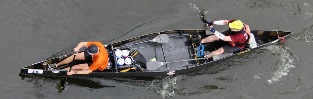
In 1971, famed Minnesota paddler and canoe racer Gene Jensen noticed that by bending a canoe paddle at the neck, where the shaft meets the blade, a paddler could move a hull faster than with an equivalent straight-shaft paddle. Jensen noted that paddlers using straight shafts, “had to dig these enormous holes, and their paddles would really cavitate. They didn’t seem to go as fast as they should.” The rest, as they say, is history. You can scarcely go to a downriver or flatwater race and not see carbon fiber bent shaft paddles everywhere. And because of their efficiency they’ve become rightfully popular with recreational paddlers as well.
So naturally, I had to ask “Why?” Why is it that bent shaft paddles are more efficient at moving a hull? Is there an optimum bend angle, and if so, what does it mean for it to be “optimal”?
To answer these questions I used a simplified physics model of how a paddle generates force to quantify “efficiency” and “optimal.” Fortunately, I also stumbled upon a nice article by Nicholas Caplan which provided valuable biomechanical data that I used as input to the model. It turns out that you maximize peak padding force and impulse (the time integral of force) if the blade is perpendicular to the water at the instant that the relative velocity between the paddle and the hull is maximum. And using Caplan’s data, based on this preliminary analysis, the optimum bend angle is 12 degrees. Subject to a few caveats.
So now that you know the bottom line feel free to move on, go train, etc. Or if you’re curious like me about the why, read on.
EIN BISSCHEN PHYSIK[1]
While Isaac Newton wasn’t a paddler, perhaps he was inspired by the punters at Cambridge when he developed his laws of motion. His Second Law states that forces acting on a body will accelerate it in inverse proportion to its mass[2]. For a hull, paddler, and paddle with a combined mass M, the Second Law may be stated as
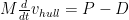
where d/dt denotes the time rate of change of the hull’s velocity[3] vhull, P represents the propulsive force exerted via the paddle, and D is the drag force acting on the hull in opposition to the propulsive force. The right-hand side of the equation is the net force on the hull. All quantities in this equation except the mass are functions of time.
We’ve discussed the contributors to the drag force D in “Part 3: The Rough Stuff.” Ultimately the components of drag – friction, form, and wave – are properties of Nature and the hull design. What we’re left to consider is how to maximize the propulsive force P to create the greatest hull speed.
The propulsive force from the paddle may be expressed in terms of the relative velocity between the hull and the paddle – in the direction of travel – as

where 
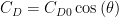
The term CD is the drag coefficient, which is a dimensionless quantity that characterizes the blade’s resistance to motion through water. It is a property of the blade design, and in the equation above is distinct from the blade area A. It is also a function of the shaft angle[4], defined in Figure 1 below.
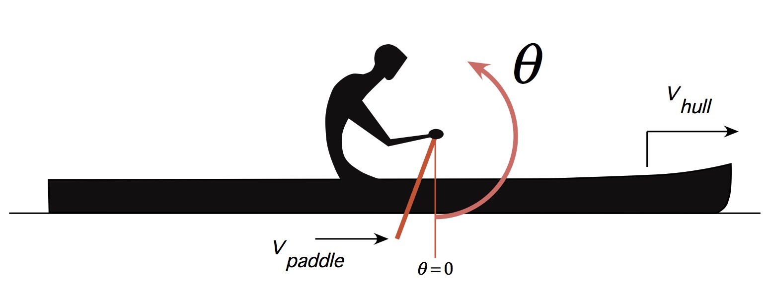
Figure 1: Coordinate definitions.
The propulsive force P has a direction that is perpendicular to the blade’s power face; force is a vector. And as paddlers all know the angle of the power face changes over the course of the stroke. Since we’re interested in the propulsive force in the direction of travel, and assuming that the center of pressure on the blade’s power face during a stroke does not move up or down[5], the angular dependence of the drag coefficient can be approximated by
where 
Nicholas Caplan employed high speed video cameras to measure the shaft angle over time, and the relative hull/paddle velocity, of an elite outrigger paddler using a straight shaft paddle[6]. Data! Now it would be natural to just dive in and use his data without thinking about it. But where’s the fun in that? Plus this provides us with an object lesson in interpreting the results derived below, or more broadly, in reading any reporting on science or engineering: read the results in light of the underlying assumptions. By using Caplan’s data we are assuming that the stroke mechanics employed by one outrigger paddler will be the same for all of the rest of us, using either straight shaft or bent shaft paddles. That’s a big assumption, so please keep it in mind. But it gives us a place to start.
While I did not obtain a copy of Caplan’s raw data, I was able to approximate it rather well using simple mathematical functions. The relative velocity he measured can be expressed by

This approximation is valid from the time of the stroke’s catch at t = 0 seconds until the exit at t = 0.4 seconds, and is plotted in Figure 2 below. The relative velocity is negative because the magnitude of the paddle velocity is greater than the magnitude of the hull velocity during the power phase, as we discussed in “Part 5: What Moves You.” It also means that the paddle velocity is directed toward the stern. (Remember our friend momentum?) The relative velocity clearly varies over time, and its magnitude achieves its maximum value just a bit after mid-stroke (as defined by the time interval between the catch and exit). Hmm… That’s very interesting. Might be worth keeping that fact in our back pocket.
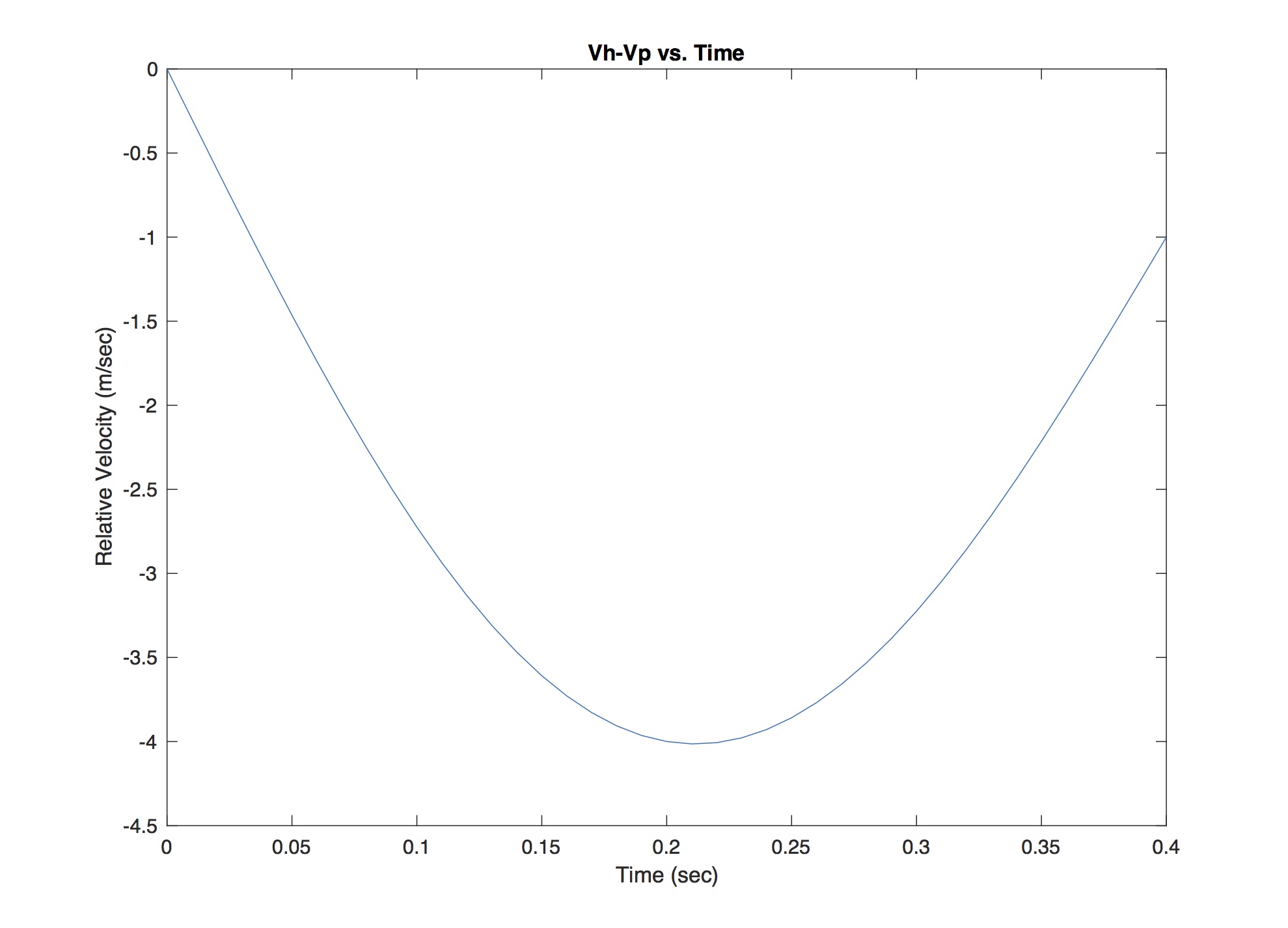
Figure 2: Relative velocity from catch to exit (after Caplan).
Caplan discovered that the shaft angle for his outrigger paddler varied linearly over time from a minimum of minus 30 degrees at the catch to a maximum of 50 degrees at exit. Consequently, the shaft angle he measured can be represented by

This angular dependence is plotted in Figure 3 below. Since it is linear, the shaft angle doesn’t show any inflection point with maximum magnitude, just minimum and maximum angles at the catch and exit.
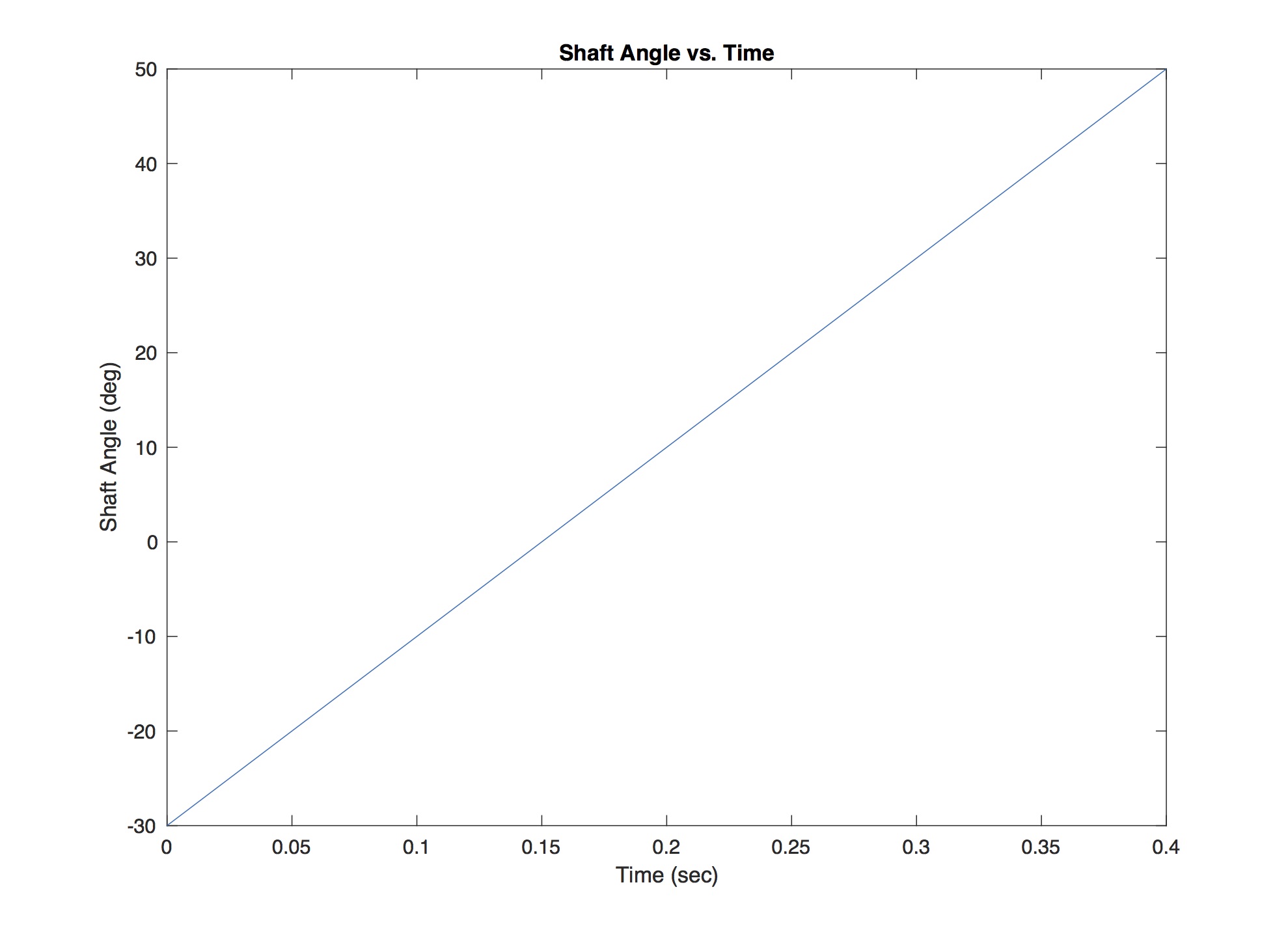
Figure 3: Shaft angle from catch to exit (after Caplan).
Given all that, it’s time to compute some paddle forces!
PADDLE FORCE AND BEND ANGLE
As shown above, the propulsive force from the paddle can be expressed in terms of the time-dependent shaft angle

In this equation we’ve introduced an additional parameter 
We know that the direction cosine and the relative velocity change over time, so it’s reasonable to conclude that we want them to reach their maximum magnitudes at the same time. Engineers call this “in phase.” You will recall from high school trigonometry that the cosine function varies in magnitude from 0 to 1. The cosine reaches its maximum when its argument is either zero or 180 degrees. Here, the zero degrees corresponds to “downward vertical,” and the 180 degrees corresponds to “upward vertical,” e.g. when doing a paddle salute.
In Figure 4 you’ll find a plot of the relative velocity’s magnitude vs time, as well as the direction cosine in the equation above based on Caplan’s data. In order to fit things nicely on the same plot, and for clarity of exposition, the direction cosines have been multiplied by 4 in this figure. The direction cosine is plotted for two values of the bend angle
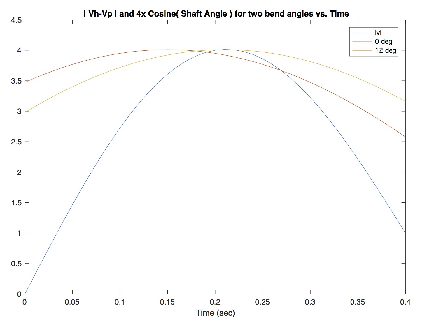
Figure 4: Relative velocity magnitude and direction cosine from catch to exit.
In Figure 5 you’ll find a plot of the resultant propulsive forces for the straight shaft and bent shaft paddles, computed using the equation above. Since we’re interested in comparing data, and not in the force’s absolute magnitude, for simplicity I set the values of the water density, blade area, and nominal drag coefficient to one. The paddle force for both cases starts at zero since at the catch you haven’t started to pull. The bent shaft’s force profile – the variation in force over time – lags the straight paddle; the bend introduces a phase lag in the force[7]. As you can see from the plot the bent shaft paddle hits a higher peak force than the straight shaft paddle, again due to this “phase alignment.” Further, it hits this peak a bit later than for the straight shaft case. This is because the relative velocity had maximum magnitude a bit later than the power phase’s midpoint, and the bent shaft’s blade is perpendicular to the water at that moment.
I had expected the peak force for the bent shaft paddle to be a bit higher in comparison to the straight. But again, we’re taking data from an outrigger paddler using a straight shaft, and extending it using mathematics to the bent shaft case, assuming all along that the mechanics are the same. Still, even in light of those assumptions, the underlying physics is true. Phase alignment is good.
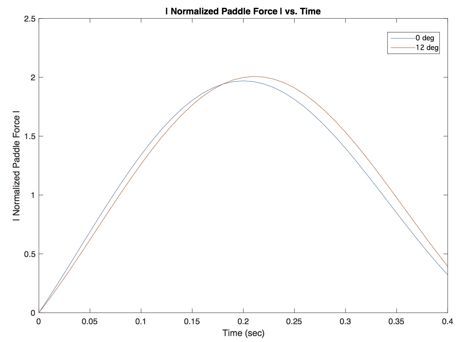
Figure 5: Normalized paddle force vs. Time.
WHAT DOES IT ALL MEAN?
So your paddle blade should be perpendicular to the water at the same time that the relative velocity between the blade and the hull is greatest. Great. Why not just cut off the stroke at that point? Wouldn’t that make the hull move fastest?
Short answer: No[8]. But great question! In order to arrive at this conclusion I took the time integral of these normalized paddling forces in order to compute what physicists and engineers call impulse. An integral is merely the area under the force curve, here from catch to exit. It captures the entirety of the power phase’s propulsive contribution, not just the peak force. Impulse produces a change in linear momentum, which as we learned in Part 5 determines cruising speed. Using Caplan’s data the bent shaft produced 2.4% more impulse than the straight shaft; in other words, you’ll go faster with the bent shaft. A bit less than I would expect, likely due to our underlying assumptions, but an increase nonetheless.
All of the above computations were done in MATLAB. I studied other bend angles than 0 and 12 degrees. But the optimum bend angle for the given relative velocity vs. time, and shaft angle vs. time, was 12 degrees. More fundamentally one would need to measure these quantities for each paddler, and then investigate how to optimize bend angle for them individually. But for a given paddle it is best if the blade is perpendicular to the water when the relative velocity is maximized. Phase alignment is good.
And for this first pass, we’ve seen that Gene Jensen was right. Bent shaft paddles are more efficient at generating greater propulsive force.
V. 1.02
Copyright (c) 2018, Shawn Burke. All rights reserved. see Terms of Use for more info.
- Well if Mozart got “Eine Kleine Nachtmusik,” why can’t physics? ↑
- Actually, the applied force changes the object’s momentum, but if the mass is constant then the equation simplifies to this familiar form. ↑
- This time rate of change of velocity is the acceleration, and d/dt is a derivative. Just dropping a little calculus. ↑
- Since the blade is rigidly affixed to the shaft, if you know the shaft angle you know the blade angle. ↑
- Pressure is a scalar (and isotropic), with units of force over area. The pressure over the blade is integrated over its area to yield the magnitude of the propulsive force. The center of pressure is determined via a centroid calculation of the pressure distribution over the blade. Once the center of pressure is known the propulsive force vector is assumed to be directed from that location, perpendicular to the blade’s power face. Fun! ↑
- Nicholas Caplan, “The Influence of Paddle Orientation on Boat Velocity in Canoeing,” International Journal of Sports Science and Engineering, Vol. 3, No. 3, pp. 131-139 (2009). ↑
- Star Wars reference, anyone? ↑
- With a caveat: Ultimately you have to take into account stroke cadence, and the relative amount of time you spend in the power phase vs. the recovery phase. Which will be the topic of a later Science of Paddling article. ↑