by Shawn Burke, Ph.D.
OVERVIEW
The question of whether cutting a circular shallow water corner saves time is explored. Turn radii criteria are derived using a Froude Number-based equal effort metric in terms of the depth-dependent surface wave phase speed. The result is recursive. The effect of spanwise current variation is considered.
WHAT DO YOU MEAN BY CUTTING CORNERS?
Here’s a question that keeps popping up from Science of Paddling Readers[1]: When is it advantageous in a race to cut a shallow water corner? Turns out this is a far more complex question than it may at first seem. To precisely answer it requires knowledge of at least the following factors:
- Are the hulls involved in the turn the same hydrodynamically, or are they different?
- Does a given hull behave differently than others when turned in progressively tighter arcs? Or does it begin to skid on increasingly tighter turns, and thus change underlying assumptions about its hydrodynamics?
- If a turn is “shallow” for one hull, is the other hull in “deep” water, or something else?
- For a given turn, does the water depth vary uniformly with distance from shore, or in some other way?
- Does the bathymetry (e.g. depth profile) vary along the turn as well as cross-stream?
- What is the shape of the turn: Circular, elliptical, or something else?
- If there is current, is the current uniform cross-stream or does it vary in some way? If it varies, does this variation apply to any and all rivers, is it river-specific, or is it specific to individual turns on any given river?
- Will the hull in shallower water be “popped,” and thus surf a nonlinear surface wave? If so, what hydrodynamic model applies?
- How do we address paddling “level of effort” between the hulls in the turn? Do the paddlers in each hull have the same paddling biomechanical efficiency, or are we only concerned with hydrodynamics?
Each of these factors introduces its own complications. Many can only be addressed via numerical simulation; this would be highly specific to a particular turn, in a particular river, and to particular hulls. Where’s the fun in that?
Instead, in order to approach the problem of cutting corners we’ll introduce a number of simplifying assumptions that yields something tractable, yet still provides insight into the problem. [2]
MAKING ASSUMPTIONS, GETTING RESULTS
Remember the Science of Paddling, Part 4: Shallow Water? You might want to give it a quick review before diving into this one.
We’ll wait.
OK, ready? Great!
In order to narrow the corner-cutting problem to something tractable, we’ll make the following assumptions:
- There are two hulls entering a turn, and they are hydrodynamically identical. This includes their trim and hull depth beneath the waterline.
- All paddlers have the same biomechanical efficiency.
- One hull takes a route through shallow(er) water, and the other takes a route through deep water – recall that in Part 4 we learned that water is deep if it is approximately half the hull’s length in depth, or deeper.
- The water depth varies monotonically from the turn’s inside to its outside. This is an implicit assumption, otherwise interpreting the results gets really weird.
- The turn is perfectly circular.
- The water depth stays constant along any given circumferential arc of the turn.
- We’ll restrict ourselves to the linear (small wave) approximation employed in Part 4, so no surfing or nonlinear wave effects. We’ll look to address nonlinear surface waves in a later article.
- Each hull will move at its own constant speed through the turn, hence we’ll neglect any transient effects from entering and exiting shallow(er) water.
- Stream flow speed and cross-stream variation in flow speed will be addressed later in the article; for the moment we’ll assume that both hulls are in a reference frame moving with any (cross-stream uniform) flow so that the stream flow speed in the reference frame of the hull is zero.
Consistent with all of these assumptions, consider the turn depicted in Figure 1. Two hulls are entering a 90-degree counter-clockwise turn at the same time, running abreast. The first will follow an arc of length P1 at a radius R1 over an angle 
![]()
Figure 1: Turn geometry, plan view.
One model of the bottom bathymetry versus radius is depicted in Fig. 2. As noted above the outer radius lies in deep water; again, “deep” means anywhere greater than about half the hull length L (e.g., L/2) in depth. The allowable range of the outer radius R2 is shown to extend from a depth of L/2 outward, consistent with the deep-water assumption for the outer hull.
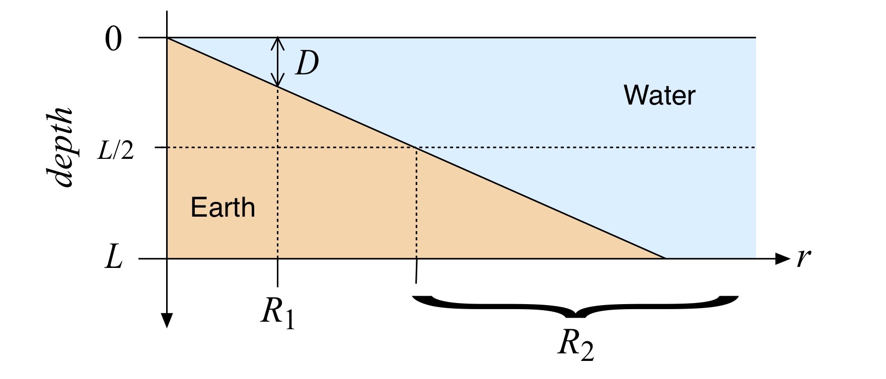
Figure 2: Turn bathymetry.
As you’ll recall from Part 4, a nondimensional Froude number[4] Fr can be defined as the ratio of hull speed V to the phase speed of surface water waves cp:

When the hull speed is greater than the phase speed the Froude number Fr is greater than 1. This means you’re paddling faster than the water surface “wants” to move, and as a result the effect of wave drag will increase. (It’s similar to how a resonator likes to oscillate at its resonant frequency; the water “spatially resonates” with objects moving over it that have length equal to the surface wavelength corresponding to the phase speed for a given depth.)
We’ll introduce another assumption: Both the “inner” and the “outer” hulls are paddled at the surface wave phase speed corresponding to their respective water depths. In other words Fr = 1 for each hull. This is one way of stating that the paddling effort in overcoming wave resistance is the same for both hulls.[5]
Given these two hull speeds – really, two surface wave phase speeds since the Froude number for each hull is assumed to equal 1 – the problem reduces to finding the radius R1 for a given inner hull water depth D that let the two hulls keep pace with each other through the turn.
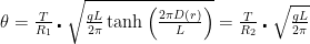
One way to characterize this is to determine how far each hull travels in a given time T, then solve for the respective radii that let the two hulls cover the same angle
where we have used the expression for the surface wave phase speed cp from Part 4 for the along-track hull speed (recall that Fr = 1). g is the acceleration due to gravity. The depth D is written as a function of the radius r; this dependence will be an important consideration in a moment.
The hyperbolic tangent function displays a nice sigmoid-like behavior as a function of its argument, with asymptotes at +/- 1, shown in Fig. 3 for an 18’6” long hull and various depths D.
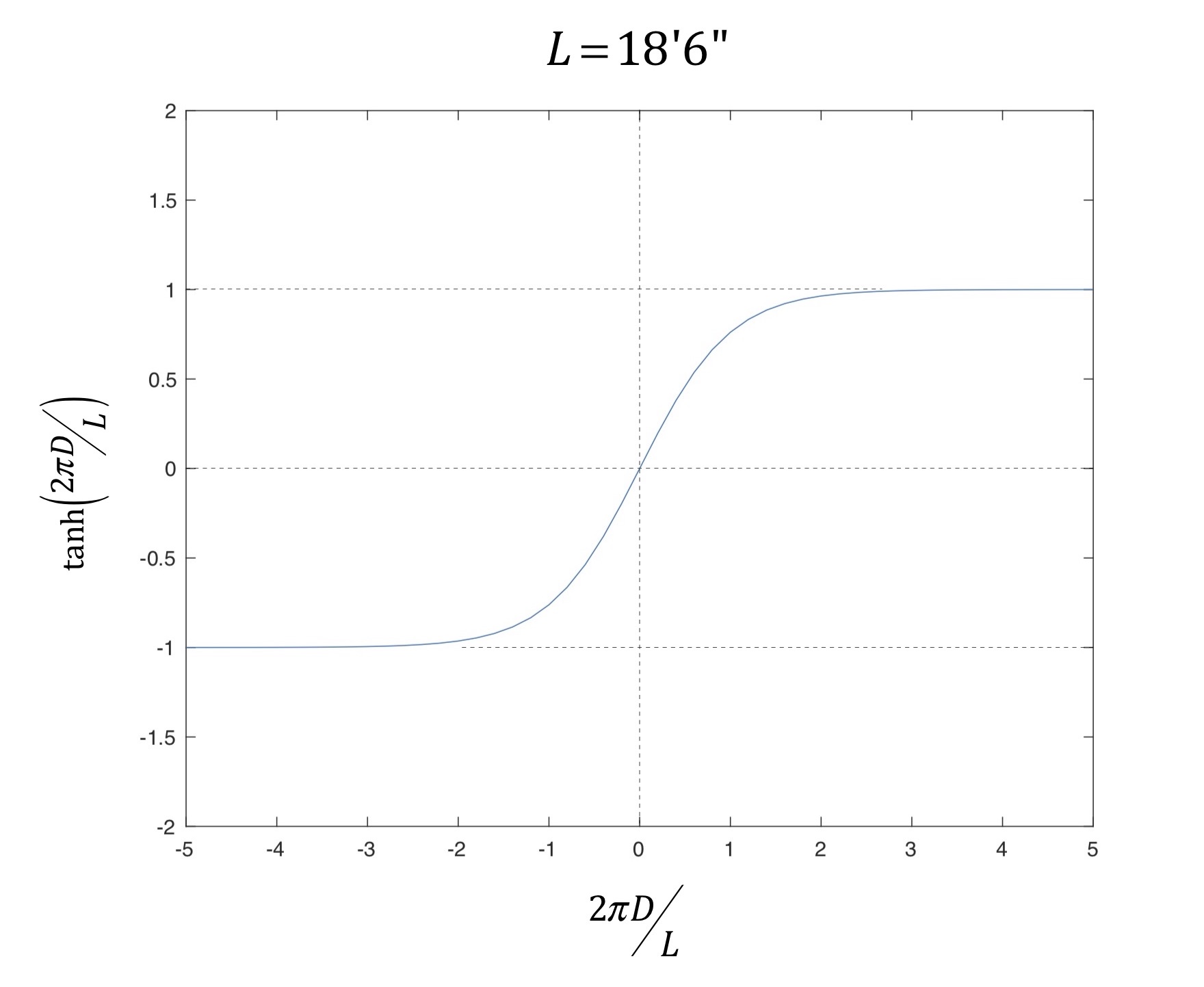
Figure 3: Hyperbolic tangent function.
As you can see in the plot, for values of its argument having magnitude[6] greater than about 3 that tanh(.) is well approximately by the constant 1. This corresponds to deep water with respect to the hull length. Consequently, for the outer (deep water) hull, the path length equals the surface wave phase speed for deep water multiplied by time:

Now the hulls are assumed to paddle abreast, hence the angle
or
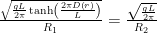
This equation then defines the inner radius one can use to “cut the corner” in shallow(er) water and keep pace with a hull further offshore paddling in deep water. It is implicit in this expression that the radius R1 is the radius at which the depth equals D. In other words, one cannot compute the expression for the surface wave phase speed for a given shallow water depth D (in the numerator on the left-hand side of the equation above) and then vary the radius R1 arbitrarily! The depth D is a function of the radius, as pointed out above; the problem is recursive[7]. Also, the radius R2 must be a “deep water” radius since the outer hull was assumed to be in deep water at that radius. And R2 must be greater than R1.
All that said, the expression above shows that in order to keep pace when the surface wave phase speed decreases due to decreasing depth (subject to all the assumptions above) for a consistent level of effort you have to paddle a progressively tighter turn in order to paddle a correspondingly shorter circumferential distance; the right-hand side of the equation is depth-independent, and fixed by the location of the outer hull’s arc and the hull length.
If the hyperbolic tangent function makes you feel all squidgy, you can use the shallow water approximation for the surface wave phase speed of the inner hull. The shallow water approximation is derived using the Taylor series[8] expansion of the hyperbolic tangent function, vis

For small values of the argument, which here means small values of depth in relation to the hull length, you just retain the first term in the series; the magnitude of the cubed and higher terms will be much smaller than the linear term and can be neglected. This is illustrated in Fig. 4, where the exact form of the hyperbolic tangent is plotted along with the simple linear approximation for an 18’6” long hull. Interestingly, the approximation is best only for very shallow (perhaps 1.5’ deep and less) water.
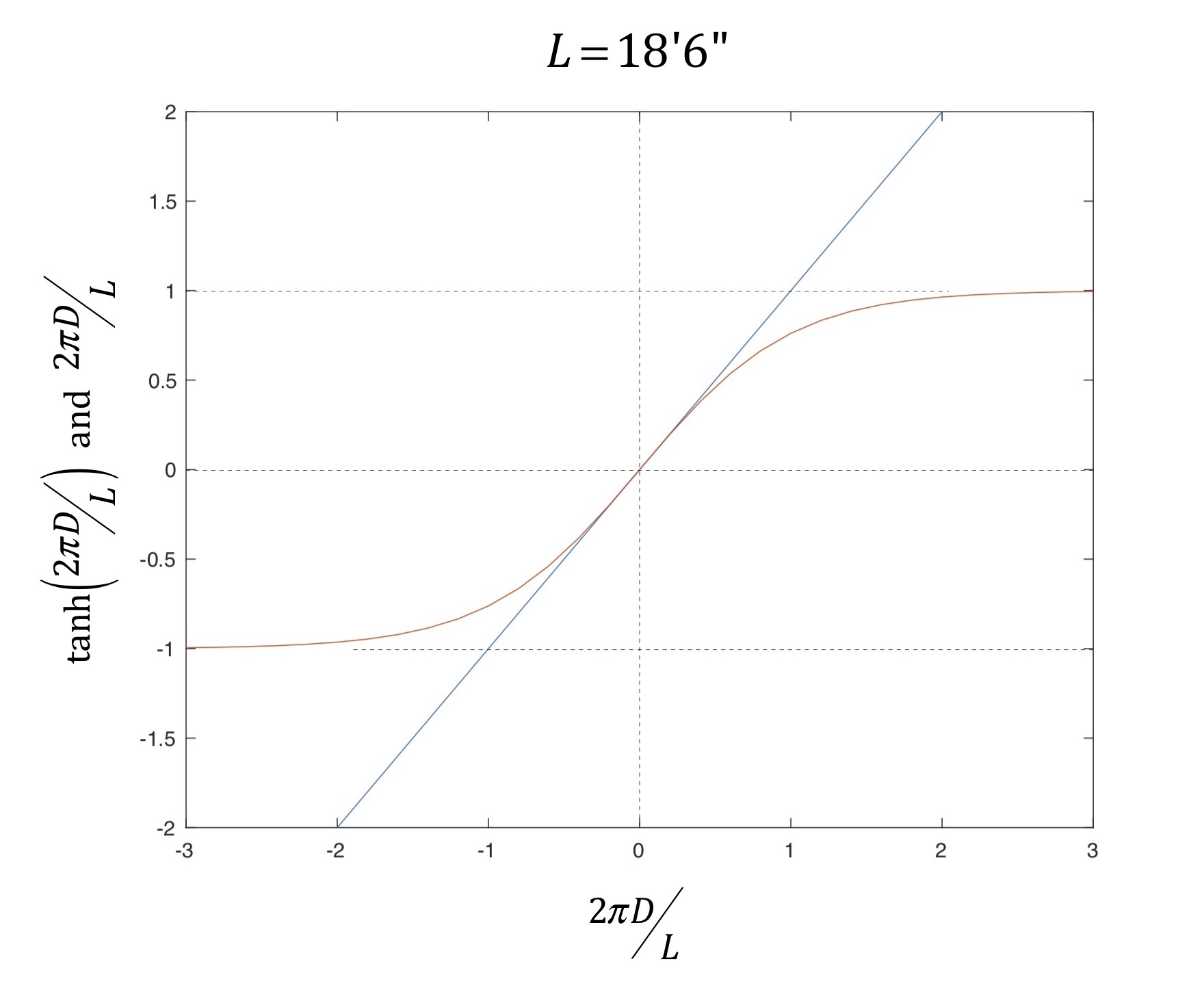
Figure 4: Hyperbolic tangent and a linear approximation.
Consequently, for an inner hull traveling in shallow water you obtain the simpler expression for the radii as

which can be rewritten simply as
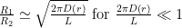
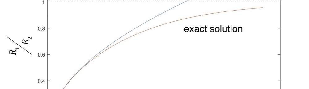
So for cutting shallow water corners consistent with the assumptions above, the turn radius that lets you keep apace with a hull traveling in deep water will vary as the square root of depth. This ratio is plotted in Fig. 5 for the approximation above, as well as for the “exact” expression that uses the hyperbolic tangent function. Fig. 5 shows that the exact and approximate solutions diverge at about 1’ of depth; above about 2.5’ of depth the approximation becomes nonsensical since it suggests the inner radius be greater than the outer radius (and thus contradicts one of our assumptions). So sorry, folks. If you felt squidgy about the hyperbolic tangent function you’d best learn to embrace it.
You can use Fig. 5 to select an inner radius R1 to cut the corner corresponding to a depth D (remember the assumptions!) with respect to the outer radius R2. Perhaps most interesting is what happens when the water depth approaches 4.5 – 5’, at or just a little deeper than so-called “concrete water.” In that case the radii ratio (using the exact solution) asymptotically approaches 1. At this 4.5 – 5’ depth the inner hull radius moves toward the deep-water radius of the outer hull. This is because both hulls are now in (effectively) deep water. Why do they become equal? Because we were solving for an inner radius that enabled the hulls to run abreast, not for an inner radius that let the inner hull emerge from the turn ahead! For deep (enough) water deciding to cut a corner is only a distance minimization game. This means that if both hulls are in deep enough water, definitely cut the corner since there is no wave drag differential between the two hulls. Otherwise, carry Fig. 5 with you and plan accordingly!
Figure 5: Radii ratio for exact and approximate solution.
THE EFFECT OF CURRENT
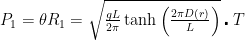
It’s straight-forward to introduce current into the analysis above. If the inner hull travels in a constant current with speed V1 throughout its turn, then the circumferential arc length it subtends over time T to keep abreast of the outer hull is simply a restatement of distance equals speed times time, where speed is now the sum of the phase speed and current speed:
![{{P}_{1}}=\theta {{R}_{1}}=\left[ \sqrt{\frac{gL}{2\pi }\tanh \left( \frac{2\pi D\left( r \right)}{L} \right)}+{{V}_{1}} \right]\centerdot T](https://s0.wp.com/latex.php?latex=%7B%7BP%7D_%7B1%7D%7D%3D%5Ctheta+%7B%7BR%7D_%7B1%7D%7D%3D%5Cleft%5B+%5Csqrt%7B%5Cfrac%7BgL%7D%7B2%5Cpi+%7D%5Ctanh+%5Cleft%28+%5Cfrac%7B2%5Cpi+D%5Cleft%28+r+%5Cright%29%7D%7BL%7D+%5Cright%29%7D%2B%7B%7BV%7D_%7B1%7D%7D+%5Cright%5D%5Ccenterdot+T&bg=ffffff&fg=000&s=0&c=20201002)
Similarly, for the outer hull
![{{P}_{2}}=\theta {{R}_{2}}=\left[ \sqrt{\frac{gL}{2\pi }}+{{V}_{2}} \right]\centerdot T](https://s0.wp.com/latex.php?latex=%7B%7BP%7D_%7B2%7D%7D%3D%5Ctheta+%7B%7BR%7D_%7B2%7D%7D%3D%5Cleft%5B+%5Csqrt%7B%5Cfrac%7BgL%7D%7B2%5Cpi+%7D%7D%2B%7B%7BV%7D_%7B2%7D%7D+%5Cright%5D%5Ccenterdot+T&bg=ffffff&fg=000&s=0&c=20201002)
Solving for the angle q, and equating things equal to the same thing yields
Assuming the inner hull is paddling in shallow water, consistent with the assumptions above one derives
which can be rewritten as
So if you know the shallow water depth D at R1 as well as the current speeds at the respective radii you can compute the radius for “cutting the corner” that keeps you abreast of the hull in deep water. Or for intermediate depths you can use the exact expression.[9]
The chief limitation in using this result is obtaining the respective current speeds V1 and V2. There are innumerable references that address stream flow in aggregate (see the References section below for examples), providing models of sedimentation transport for a given streambed and flow rate, flow rate as a function of level, etc. But none of these provide cross-stream flow speed data or models. If you have the flow speed data you can crunch the numbers. Otherwise you’re left with making assumptions that likely won’t generalize across a set of rivers, or even turn-to-turn for a given river.
SUMMARY
In this installment of The Science of Paddling we considered the question of whether cutting a circular shallow water corner saves time, or at least keeps you abreast of a hull in deeper water. We derived a turn radius criteria using an effort-relevant metric derived from the depth-dependent surface wave phase speed. The radius you can paddle to keep apace varies as the square root of depth if you’re already in shallow water; for other water depths it’s a little more complex. Further, the result is recursive, for reasons noted above. Don’t forget your calculator! Or bring along a copy of Fig. 5.
The effect of spanwise current variation was considered, with the ensuing “corner cutting criteria” shown to require field data from actual streams and turns. Otherwise the analysis is unchanged.
Like many articles in the Science of Paddling series we’ve once again shed light on the why. It’s a bit more difficult to use the results above predictively unless you do some highly detailed scouting to determine the bathymetry of each and every turn on a course. It’s probably easier to just find someone who’s intimately familiar with the course, hang on their stern, and (as they say) settle it in the last mile.
Then again, if you’re interested in mapping out the course and doing some calculations, please share your results with us!
v1.0
(c) copyright 2020, Shawn Burke, all rights reserved. See Terms of Use for more info.
REFERENCES
Luna Leopold and Thomas Maddock, Jr., “The Hydraulic Geometry of Stream Channels and Some Physiographic Implications”, Geologic Survey Professional Paper 252, United States Government Printing Office, 1953.
Jud F. Kratzera, Daniel B. Hayesa, and Bradley E. Thompson, “Methods for interpolating stream width, depth, and current velocity”, Ecological Modelling 196, pp. 256–264 (2006).
- Hi Readers! ↑
- And as we’ve seen in the article “Where’s the Science?” these assumptions must be kept in mind at all times, not only during the derivation here, but in how you the reader look at and interpret the results. ↑
- In truth for the ensuing analysis the angular sweep of the curve can be whatever it wants to be, consistent with all of the stated assumptions. ↑
- Note that we’re saying a Froude number. You can define the Froude number in other ways, just like you can specify the Reynolds number in fluid mechanics in a variety of ways. As long as you’re clear on what quantities are used to define the Froude number you’ll be fine. ↑
- Which further assumes that the paddler(s) in each hull have the same paddling biomechanical efficiency. See; these assumptions pile up! ↑
- We’re only concerned with positive values of the depth; who knows what a negative depth is? But the hyperbolic tangent function itself allows both positive and negative arguments. Plus the plot is pretty. ↑
- Here, this means that if you solve the equation as written for the inner radius R1 you end up defining this radius in terms of itself, since depth D depends on R1. ↑
- Technically this is a Maclaurin series since we’re expanding the function about x rather than (x – a). But Taylor gets all the credit. And I’m being pedantic. ↑
- You can simplify either result a bit by using the difference in speed between the two hulls, defining a new speed V3 as V2 – V1 and thereafter setting V1 to zero; this means you’re transformed the problem to an inner hull-centric coordinate frame. ↑